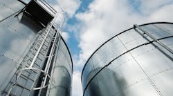
Tanks come in different types, sizes and configurations and play diverse roles at process plants. They store feedstocks and final products as well as intermediates and semi-finished material. Most tanks at chemical facilities are above-ground welded-steel units; stainless and alloy steels, concrete and other materials also find use.
The design, construction and operation of tanks require great care because leaks, spills and loading/unloading can present safety and environmental risks. Large storage tanks for process liquids demand particular attention in design and selection of construction material. Tanks should undergo rigorous checking and testing before going into operation. In addition, they should have a containment area or retaining wall (bunding) that provides at least the capacity of the tank. While leaks shouldn’t happen, it’s prudent to prepare for the worst-case scenario.
Types Of Tanks
Tanks fall into two general categories: pressurized and atmospheric pressure. Pressurized tanks usually store liquids that evaporate. Tank types can be broken down further into fixed-roof and different types of floating-roof variants.
Tanks inside process units typically are medium/small size that provide several hours of hold-up. Large storage tanks usually reside outside process battery limits on tank farms or offsite areas, and generally hold at least a day’s worth of material. Time variations in supply of raw materials and demand for products influence the size and number of storage tanks. Larger storage tanks have gained increasing favor in recent decades; because of this, the loadings and design (such as for seismic events) for these larger storage tanks has become more important.
Many storage tanks sit on earth foundations with a concrete ring at their periphery. They may not have anchoring devices.
Now, let’s look at some common types of tanks.
API tanks. The American Petroleum Institute (API), www.api.org, has established standards for tanks. API-650 provides minimum requirements for above-ground steel cylindrical storage tanks roughly equal to the pressure of the atmosphere (not greater than the weight of the roof). By meeting additional requirements, higher internal pressures are allowed. API-620 suits products such as liquefied gases that have high internal pressure to store contents at, say, a maximum of 1 barg, as well as services involving cryogenic temperatures.
Fixed-roof tanks. Liquids stored at near-atmospheric pressure may experience breathing losses. Tank cooling during the night may draw air in, then vaporization occurs to saturation, followed by expulsion of the vapor mixture as the tank warms up during the day. Volatile liquids consequently suffer a material loss and also a change in composition because of the selective loss of lighter constituents.
Floating-roof tanks. These find wide use to minimize the effects of breathing losses. A pad floats on the surface of the stored liquid/fluid. It has a slightly smaller diameter than that of the tank (as a very rough indication, 20–40-mm less). One of several available methods seals the annular space between the float and the tank shell. Typically, a seal is attached to the roof perimeter and contacts the tank wall/shell, reducing evaporative loss of the stored liquid. The seal system slides against the tank wall as the roof goes up and down with the liquid level in the tank.
Many working liquids, including numerous hydrocarbons and other chemicals, emit extremely volatile vapors that pose combustion, toxicity, pollution or other risks — and that collect in the space between the roof and the liquid. The rim seal on the floating-roof tank keeps these emissions from escaping into the environment. It’s possible to install mechanisms to capture this vapor, enabling its use at the plant, sale to interested parties, etc.
Floating-roof tanks come either with an external floating roof and or an internal one. An external floating roof consists of a deck, fittings and rim seal system. Decks are of three general types: pan, pontoon and double-deck — with pontoon and double-deck types now more favored. An internal floating-roof tank has a permanent fixed roof as well as a floating roof inside.
A floating roof may not function normally if the rooftop is out of balance or the tank body distorts. Many cases of sunken roofs have occurred. For instance, the roofs of several external floating-roof tanks sank after heavy storms — for a variety of reasons (low capacity of the roof drain, etc.). External designs are more prone to such risks.
Tank Design
This is complex and can be challenging and confusing. Many loading cases and scenarios usually require simulation and proper evaluation. Besides all possible internal pressure situations, the designer may need to consider wind, seismic and potential vacuum cases as well as dead and live weights from structure/platforms, thermal loads, settlement conditions (differential, tilt, etc.), critical loads during tank installation (usually short term) and others. Different formulations and approaches, such as the “1-foot method,” “variable point method,” etc. (in API-650 or other codes), can calculate shell wall thicknesses (shell courses) and finalize the design of a tank including details of roof, roof-shell junction, etc. Today, you can use advanced software for tank design.
For high or low operating temperatures, the allowable stress of the material decreases. As a result, the required wall thickness increases. This relationship often is slightly nonlinear but linear methods can provide a rough estimate. In addition to causing hoop stress and longitudinal stress in the tank wall, the slight internal pressure creates a tensile force (pressure × area). This force pulls upward on the tank wall. The weight of the tank and roof counter this force. If the net force is upward in any operating case or condition, you should install anchor bolts to hold the tank down.
An often-overlooked scenario is the possibility of the tank experiencing a slight vacuum. This generates a compressive stress in both the hoop and longitudinal directions — and can represent a potentially severe condition, particularly for large thin-walled tanks that might be vulnerable to buckling. It mandates checking all possible buckling modes and computing the allowable compressive stress at each point of concern and comparing it to the actual compressive stress.
Determining the maximum allowable working pressure for both the internal and external (vacuum) pressure cases usually is required. This involves iteratively changing the pressure until extreme pressures are found for the tank.
Seismic loading cases generally are critical ones for many tanks, particularly large thin-walled ones with heavy liquid content. For the seismic analysis, you should consider fluid/structure interactions. The seismic loading closely relates to sloshing of the liquid content in a tank with the tank base subjected to a horizontal and vertical ground motion. Usually such an analysis requires use of an advanced finite element method.
Dynamic loadings such as seismic loading cases can create different failures/buckling modes for tanks. The failure mode from a seismic force varies from tank to tank. It might be a buckling of the cylindrical shell, e.g., so-called “elephant foot bulge” mode or “diamond pattern buckling” mode.
Because tanks in chemical plants often contain large volumes of combustible, toxic or otherwise hazardous materials, they pose substantial risks. Indeed, tanks have caused many significant incidents. A small accident may lead to multi-million-dollar property loss, costly production interruption and expensive spills or other environmental damage.
Coping With Lighting
Traditionally, tank accidents most frequently arise from lightning. Lightning-related fires generally stem from one of two causes: a direct strike or its secondary effects, such as the bound charge, electromagnetic pulse, electrostatic pulse and earth currents. When a storage tank is in the direct strike zone, flammable vapors exposed to the heating effect or the stroke channel may ignite. In some cases, a direct lightning strike on a tank has resulted in its roof blowing off and massive destruction.
A storm cell induces a charge on the surface of the earth and structures projecting from the surface under the cell. This charged area varies in size but is relatively large — much larger than the direct strike zone. The risk of a secondary-effects-related fire far exceeds that from a direct strike.
The rim seal of a floating-roof tank is the most likely place for ignition. Therefore, tight sealing to prevent the escape of vapors and fluids is essential for safety. The vent valve also a likely place. So, you always should install a flame arrestor. Ideally, lightning protection of a tank should exceed the requirements of existing lightning-protection standards because such conventional standards often aren’t adequate to deal with extreme cases.
Preventing Human Errors
Traditionally, maintenance error is the second most common cause of tank incidents. Other culprits include equipment failure, crack and rupture, leaks and piping breaks, static electricity, open flames, etc. Good engineering and site practices could have avoided most of these accidents.
Catastrophic failure of a tank potentially can occur when flammable vapors in the tank catch fire or explode. Welding operations on the outside of an operating tank or one not purged properly as well as sparks from hot works (e.g., using a cutting torch or grinder) on a nearby piece of equipment have led to many accidents. Mechanical friction produced during installation, maintenance or repair also can generate sparks that can ignite flammable vapors.
Hazard reduction measures are important to prevent such incidents. These include stringent hot-work procedures, such as requiring a permit, having a fire watch and ensuring the presence of fire extinguishing equipment, as well as proper testing for explosivity, and covering and sealing all drains, vents, manways, open flanges, etc.
Incidents also have happened where flammable liquids trapped in the seal ignited during a tank cleaning operation. Many fires have occurred while cleaning supposedly empty tanks of explosive/flammable liquid that weren’t purged properly. Sometimes the cleaning chemicals themselves ignited. Electric sparks and shocks also can ignite flammable vapors or liquids, resulting in fire or explosion.
In addition, problems can arise from operational errors — with overfilling the most frequent culprit. When a tank containing flammable liquid overfills, fire or explosion usually is unavoidable. Any spark nearby may ignite flammable vapor released from the tank. Sometimes vapor from an overfilled tank will travel to an ignition source (such as a flare, boiler or furnace stack, incinerator, heater, automobile engine, etc.) and then ignite. Overpressure also causes many incidents and much damage. Correct operational procedures could avoid such risks. In addition, installation of a more-effective gas detection and emergency isolation system could prevent or mitigate such accidents. (For details on gas detection, see “Ensure Adequate Fire Protection.”)
During normal operations, most tank damage stems from age deterioration, corrosion and seismic motions. Many tanks suffer cracks. Often these cracks occur at the tank bottom or the edges of welds. Corrosion can afflict tank bottoms and defective welds. Welds also can fail.
Failure of valves, instruments and other connected equipment can impact tanks. Indeed, problems such as frozen valves (unable to close, open, etc.), vent valve failures, burst valves, etc., have caused many instances of damage to tank systems. Heating of viscous or heavy liquids (such as heavy oil) to increase their fluidity has led to other incidents when a heater malfunctioned or an instrument/thermostat failed. This led to fluid overheating that resulted in flammable vapor release and further risks to the tank.
AMIN ALMASI is a mechanical consultant based in Sydney, Australia. Email him at [email protected].


