Part 2: Your Cooling-Water Exchanger Is Failing Slowly
As I mentioned in my previous column, cooling-water exchangers in many facilities are not monitored continuously and rely on engineers or operators to take field readings. The worst exchanger I measured involved monthly checks on the 300-foot-high top deck of a continuous catalytic regenerator (CCR) structure. For this reason, sometimes the data can be suspect if it requires human tabulation or more extreme effort.
The temptation for a young intern or technician to “fill it in” with similar values from previous months or days can lead to missing issues. When technicians use measurement tools incorrectly, they can introduce further gaps in monitoring. For instance, infrared (IR) temperature gun can measure the process inlet and outlet as well as the cooling-water inlet and outlet. To ensure accurate IR gun readings, technicians should compare surface temperature measurements against the process fluid temperatures reported from thermowell-mounted indicators at the operating console.
This way, a correction factor can be inferred instead of using the raw IR gun temperature measurement. Surface conditions affect IR readings, too. Coated or painted piping and measurements taken in direct sunlight can both skew results in these spot checks. That’s why it’s important to compare temperatures from a “skin” or IR on an exterior to the thermowell temperature measuring the fluid inside the pipe.
Smarter Cleaning Methods
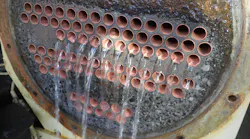
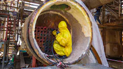
Servicing the cooling-water exchanger on the tube side allows for easy maintenance. On most exchangers, it only requires removing the channel head. Technicians can also use the hydroblasting technique for cleaning. Hydroblasting uses a stream of water at 4,000-30,000 psi to remove debris or crust/scale inside the tube walls. However, this method may not remove all the scale deposits. In these cases, an acid treatment is necessary to soften or remove the deposited scale entirely. However, use caution when cleaning with acid because the tubes themselves can be susceptible to accelerated corrosion or leaks caused by acid that does not continuously flow. The concentration of acid (pH) must be controlled to the point where it is not corrosive or where flow can be confirmed to ensure that a stagnant zone doesn’t develop to cause the accelerated corrosion.
I also recommend taking a sample of the foulant to test for the possible source, which could be suspended solids, chemical byproducts, trash or mineral scale. Tracking the fouling mechanism over time can lead to a better plan in the future. Other mitigation measures include adopting an inherent exchanger design, modifying the cooling-water chemistry or changing the exchanger network to lower the process inlet temperature.
A design with excess capacity can help reduce fouling. One good strategy involves the use of two parallel 70%-80% design exchangers. The idea is that you have exchangers that when combined (75% + 75% = 150%) are about 50% above the design heat load needed for normal process operation. This way, when one exchanger is taken out for maintenance there’s still 75% heat duty capacity available. It also allows for the use of only one exchanger at reduced rates when online maintenance is desired. In this configuration, the technician can remove one exchanger from service while the other supplies the cooling needed for the process unit at reduced throughput. Otherwise, the operations team may need to take the entire unit out of service complete the necessary cleaning. For either strategy, monitoring is critical to identify a cleaning threshold that doesn’t cause unplanned capacity losses.
Post-cleaning Tracking
When technicians mechanically clean an exchanger during a scheduled outage, they typically see pressure drop return to normal, heat transfer performance recover, process outlet temperatures decrease and unit operating flexibility improve.
Additionally, engineers should track these items after cleaning a cooling-water heat exchanger:
- Calculate performance at the end and start of each cycle
- Monitor cooling water chemistry at the time of cleaning
- Develop fouling indicators from historian data
These items help establish performance-based cleaning criteria. But if other operating regimes reduce rates during certain periods, consider using a time-based cleaning approach.
Depending on operating frequency, multiple cleanings might be necessary throughout the year. There have been several times throughout my career where we performed exchanger cleanings during non-routine times. Some of examples of unscheduled cleanings include certain crude slate runs at a refinery (sweet vs. sour crude or coker feed vs. asphalt production,) where certain products of the distillation leave slack capacity in some units; delayed coker decoking operations, whether pigging or spalling, where the unit is at reduced rates; CCR regenerator downtime; jet vs. kerosene runs on a specific distillate hydrotreater; periods before gasoline-transition season (moving to higher-vapor-pressure gasoline); and air-cooled heat exchangers (fin-fans) during winter.
Lessons Learned
Throughout my career, I’ve learned heat-exchanger fouling is typically a gradual failure mechanism rather than a sudden event. Small changes in exchanger performance can indicate significant underlying degradation. Routine performance monitoring is critical because it can identify fouling long before operational limits are reached.
Also, cooling-water quality management is essential for maintaining exchanger reliability. In my experience, I’ve seen both performance-based maintenance strategies and fixed-interval cleaning programs prove to be effective.
About the Author
 David Shivers
Process Engineering Manager, ExxonMobil Joliet
David Shivers is a process engineering manager at the ExxonMobil Joliet refinery. He is a 2008 University of Cincinnati chemical engineering graduate. His career has spanned multiple technologies and businesses, starting with his first co-ops at a BP (then INEOS) ammonia and acrylonitrile plant and then refineries with Marathon Petroleum and Phillips 66 in multiple locations. His background is primarily in process engineering for refining technologies, including sulfur, hydroprocessing, FCC, naphtha and steam methane reforming. He also held roles in operations followed by a business planning and economics position early in his career. David has mentored numerous young engineers, interns and co-ops at each of his stops. Developing the next generation of process engineering skills in refining is a passion of his. David looks forward to passing on his learned wisdom to improve engineering outcomes for those willing to take a listen.