Your Cooling Water Exchanger is Failing Slowly
I first encountered cooling water exchanger fouling as an intern at an ammonia plant. I was expected to measure the inlet and outlet temperatures for the process and cooling water.
Cooling-water exchangers are a constraint in many process units within the refinery I work in today, including overhead coolers for fractionating towers and debutanizers, rundown coolers to protect tanks, lube-oil coolers and condensers for steam turbines.
These limits have led to rate reductions that cost millions of dollars across various process units. One specific example was a depropanizer in a gas plant on the back end of an FCC. Fouled overhead coolers caused rate reductions on the FCC, crude unit and on conversion targets for other intermediate units.
The site didn’t have continuous or routine cooling-water monitoring adequate to detect the issue before the summer months. This led to a challenging discussion: Is it better to take the entire tower out of service to complete the cleaning, with a known loss of throughput? Or is it better to run at reduced rates for the entire summer until we reach ambient conditions that allow the exchanger to be cleaned without loss?
Had the unit been monitored to detect the degradation in cooling-water performance, the site could have cleaned the exchangers before the weather made a significant impact.
Recognizing the early warning signs of a fouled exchanger and understanding how to diagnose the problem using the data you already have can help you avoid similar problems.
Shoelaces and Other Fouling Culprits
A typical cooling water heat exchanger normally will operate with stable performance. The exchanger will provide cooling for a process stream using plant cooling water supplied at approximately 85°F. Different process streams can be cooled by water from a cooling tower, including hydrocarbon liquid, hydrocarbon vapor, steam condensate, natural gas, hydrogen, fuel gas, LPG, distillation tower overhead vapor in condensing service, lube oil, seal oil, compressor discharge gas, compressor spillback vapor and many other process streams.
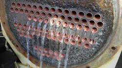
Fouling in a cooling water exchanger can occur on either side of the exchanger. Most often, cooling water is on the tube side of a typical shell-and-tube exchanger. This is because the most fouling-prone service travels through the tubes because the velocity is higher. If the velocity is too low, deposits can form, leading to fouling. It is common for trash — yes, literal trash like potato chip bags, bottled water caps, shoelaces, you name it — to settle in an exchanger, especially if the cooling water is on the shell side and must navigate around baffles. If the velocity is too high, corrosion can form, but that can be managed by tube metallurgy and cooling water chemical treatment.
Early Warning Signs
The earliest indication of a developing problem is not a sudden equipment failure but rather a slow degradation in heat-transfer performance. Key variables to monitor that can indicate fouling are:
- Increasing process outlet temperature
- Decreasing exchanger heat duty
- Rising cooling water return temperatures
- Gradual increase in exchanger pressure drop
- More frequent operator interventions to maintain process targets
Because degradation is gradual and data collection is infrequent or unreliable, heat-exchanger performance loss can be attributed to seasonal changes in cooling water-temperatures. Humidity and ambient temperature can significantly change the cooling-water temperature by 20°-30°F, so it’s important to have consistent data analysis of the exchanger performance relative to seasonal changes. This will help you identify a cooling water fouling problem early.
Flow Analysis Techniques
Process engineers can review historical operating data and calculate the exchanger's overall heat transfer coefficient (U). This analysis will typically reveal a steady decline in heat transfer efficiency over time.
Engineers should make additional checks in the evaluation, which include:
- Measuring the cooling water flow with a portable ultrasonic flow meter. I used this tool in my first internship with a refinery in Texas. It measures the flow rate in gallons per minute. This can help in the U-value calculation by checking the flow rate of water. It can also be used to diagnose cooling-water pump problems by checking pumps in parallel or individual spare pumps to confirm the flow rate isn’t changing. Other hydraulic issues can cause the flow rate to deteriorate suddenly. Throughout my career, I’ve often witnessed a “metal obstruction”— a clever way to say a valve is partially closed when it should be open and impacting the flow rate.
- Confirming the specific gravity of the process fluid. Process flow rates are consistent. A change in process stream composition can alter the process flow rate or heat capacity, resulting in a change in the process-side duty. This can be observed with temperature changes on the water side, but the differences may seem unexplained.
- Ensuring cooling water supply temperatures are within normal seasonal ranges. It’s good practice to monitor the wetbulb approach for the cooling-tower water-supply temperature. As an intern, I had to take this measurement daily using a psychrometer. I had to use one that I spun around in circles. Now, digital instruments are available.
These checks, in addition to routine monitoring, should expose resistance to heat transfer developing within the exchanger.
Catch the ‘Death Spiral’ With Inspections
A visual inspection during a planned outage can show significant fouling on the cooling-water side of the exchanger tubes. Deposits will consist of a combination of:
- Biological growth
- Corrosion byproducts
- Mineral scale deposits
- Suspended solids accumulation
The fouling layer acts as an insulating barrier between the process fluid and cooling water, reducing the exchanger's heat-transfer capacity.
The consequences extend beyond the exchanger itself. As exchanger performance deteriorates, process temperatures increase, downstream equipment operates closer to design limits, energy consumption increases, production flexibility decreases and risk of unplanned downtime increases.
Operators will compensate by maximizing available cooling water flow where possible, but these actions provide only temporary relief. Some poor examples of temporary mitigations include:
- Injecting emergency, fire or potable water into the cooling water. Often, a refinery/chemical plant emergency water system operates at a higher pressure than the cooling water. Throughout my career, I’ve seen the use of exotic manifolds to inject more water supply to the exchanger to manage a reduction in its cooling effectiveness. This can create other problems because the exchangers may not be designed for the potentially higher pressure. The tubes or shell can become overpressurized, causing a leak. Fire-water sources sometimes lack the chemical treatment found in the normal cooling-water circuit. Switching to fire water could trigger a death spiral of overdependence on the resource, which increases the exchanger’s fouling rate and leads to unplanned outages.
- External cooling with sprayed water. Depending on the location, this technique is often associated with a locally derogatory term. I’ve heard them referred to as “Arkansas coolers (when in Texas), Ashland coolers (from a merger between Marathon and Ashland) or “swamp coolers.” This can help with cooling, but not very much. It also leads to scale accumulation on the exterior of the exchanger, which can cause external corrosion or other risks.
Eventually, the exchanger will no longer provide sufficient cooling capacity to support ideal operating conditions.
Root-Cause Analysis
There can be several factors contributing to degradation in cooling-water exchanger performance directly related to fouling or to issues that can cause or worsen it.
Elevated levels of suspended solids and biological activity within the cooling water system is one potential factor. These conditions accelerate deposit formation on heat transfer surfaces. This can be caused by inadequate blowdown or by leaks into the cooling water system.
Also, cooling tower treatment records could show periods where biocide and scale inhibitor performance is below target levels, allowing biological growth and scale formation to develop. The operating conditions of the exchanger can also exacerbate the issues with cooling water.
Film temperatures on the tubes exceeding 120°-140°F can lead to deposits on the tubes and accelerate fouling. Undersized exchanger capacity, usually when unit process rates increase over time, is a common cause of temperature increases. Without upgrading the utility systems to accommodate the higher process rates, inadequate cooling water flow will lead to high-temperature film.
Process streams that haven't been cooled enough by an upstream exchanger can cause the same problem by arriving hotter than the cooling water exchanger was designed to handle. Alternatively, removing an upstream exchanger from service for maintenance or another issue can lead to higher process inlet temperatures. These short-term conditions can lead to high fouling rates in cooling-water exchangers.
Once you know where fouling comes from, the harder question is how to catch it in time. Next time, we'll cover monitoring gaps and cleaning strategies.
About the Author
 David Shivers
David Shivers
Process Engineering Manager, ExxonMobil Joliet
David Shivers is a process engineering manager at the ExxonMobil Joliet refinery. He is a 2008 University of Cincinnati chemical engineering graduate. His career has spanned multiple technologies and businesses, starting with his first co-ops at a BP (then INEOS) ammonia and acrylonitrile plant and then refineries with Marathon Petroleum and Phillips 66 in multiple locations. His background is primarily in process engineering for refining technologies, including sulfur, hydroprocessing, FCC, naphtha and steam methane reforming. He also held roles in operations followed by a business planning and economics position early in his career. David has mentored numerous young engineers, interns and co-ops at each of his stops. Developing the next generation of process engineering skills in refining is a passion of his. David looks forward to passing on his learned wisdom to improve engineering outcomes for those willing to take a listen.