Revamp A Crystallizer Revamp
This Month's Puzzler
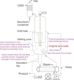
We replaced our draft-tube baffle crystallizer for borax (see figure) six months ago and have suffered a slew of severe problems ever since. Fortunately, the downstream wash-crystallizer can make up some of the production. However, we’re under the gun to fix this as soon as possible because we’re planning to increase plant capacity.
We’re seeing severe corrosion in the propeller; fouling in the draft tube; build-up in the elutriation leg above the steam heat exchanger; fouling in the level measurement float in the settling area; and scaling in the bottoms heater.
Looking at the scant files the corporate engineer left behind makes me concerned. The goal of the project was to increase the output of the crystallizer 50%. This was met in a peculiar way: 1) the volume of the settling area was raised without increasing the agitator power or impeller; 2) the cooling water goes through the same control valve although the coil in the condenser is larger; 3) the volume of the condenser only has been boosted by about 30%; 4) the crystals are larger than desirable, and our product pump is tripping frequently — erosion destroyed the new pump in 8 weeks; 5) now, we’re concerned about the feed pump; 6) steam fouling is much worse but we haven’t changed the water treatment in the boiler; and 7) the clarifier (the narrow area between the inner and outer wall) has fouled four times in six months.
Corporate has clammed up. However, I am getting help from the company that built the original crystallizer. It says the design of the new unit, which was built overseas, is a mess but can be modified to work.
Is the crystallizer company just bad-mouthing the competition or do you think it can fix the unit? Do you suggest any changes to the setup? Should we go to the fabricator of the new unit to try to get it to address the problems under warranty? What else should we consider?
Make Proper Modifications
Although the inquirer supplied a considerable amount of information, some assumptions are necessary for this preliminary analysis. As I understand the situation, the plant achieved a 50% active volume increase on the existing draft-tube-baffle (DTB) crystallizer by extending the straight side of the vessel, eliminating the cone but not changing any mechanical details on the draft tube, agitator and baffle area. The updated figure reflects this.

Figure 1. Ill-conceived modifications have led to a variety of serious difficulties.
As a crystallizer consultant, I often have worked on DTB- and Oslo-type crystallizers, including ones for processing of borax. My comments are as follows:
1. It appears that the modifications now make the unit function as both a DTB and modified growth/Oslo unit.
2. The lack of modifications of the draft-tube (DT) location and agitator means the bed of crystals at the bottom is not fully suspended and, thus, is well above the crystal bed. The additional 50% active volume without more circulation increases the temperature rise around the draft tube, which significantly boosts supersaturation — resulting in severe encrustation/scaling throughout the circuit, including the vessel bottom, baffle, fines destruction piping and the heat exchanger.
3. Because the bottom of the vessel is not fully circulated, the unit is acting like a modified Oslo (fluid-bed crystallizer), which can grow large crystals that swirl around, do not reach the boiling surface where the highest level of supersaturation occurs, and exit out of the elutriation leg based on particle-size-distribution/settling velocity. The leg is susceptible to encrustation due to the high level of supersaturation. The larger particle size distribution can cause damage to the product pump. Although not mentioned, the improper location of the feed type perhaps was an attempt to provide some mixing in the bottom settling zone.
4. The result of the increased supersaturation is that the mother liquor and some of the slurry exit into and salt up the baffle area because it originally was designed with a small area between the baffle and inside wall. Another problem is the location of the feed pipe; by not actually going into the draft tube, it potentially is leading to fines short-circuiting around the draft tube, causing entrainment at the surface and high levels of supersaturation.
5. You should measure the wt-% fines in the fines destruction loop. The baffle area was not modified, so, a much higher wt-% solids than in the original design is likely; this can result in baffle plugging plus erosion of the circulating pump and heat exchanger. For many systems, the fines destruction circuit should have less than 1 wt-% solids. Although not mentioned, I assume the flow rate in the fines destruction circuit has been increased.
6. The issue concerning treatment of the condensate at the boiler most likely is due to tube failure in the heat exchanger because of abrasion with a large wt-% solid in the fines destruction unit. In my experience, I have found that borax is an abrasive crystal that can erode pump impellers, DT impellers, plus heat exchanger tubes and tube sheet.
7. Although not mentioned, I assume the heat exchanger was not changed, and perhaps is old and subject to erosion.
If a simple fabricator made the modifications, it usually only provides a mechanical warranty and no process warranty. It often does not have the technical background to properly design a unit.
The unit requires a detailed investigation regarding the current operating parameters as well as some significant modifications to correct the apparent design and operational deficiencies.
Wayne J. Genck, crystallization consultant,
Park Forest, Ill.
Review The Scale Up
Key variables that control crystal size and distribution include: slurry density, supersaturation, crystallizer geometry including diameter of impeller/diameter of the crystallizer, impeller tip speed, circulation rate as well as pressure and temperature. In scale-up, you should attempt to maintain as much geometric and operational similarity as practicable.
Consider the following:
• Ensure the levels of supersaturation and slurry density of the scaled-up equipment are close to those for the original set-up. In addition, poor agitation, or shear, would contribute to larger crystals. Evaluate scale-up of the agitator (power per unit volume, impeller diameter, and locations).
• Crystallizer pressure and temperature also affect crystal size. So, keep them the same in the scaled-up equipment as in the pre-scaleup equipment. You will need to do a heat/material balance to get an estimate of cooling load on the overhead condenser and the vacuum system.
• Lower rates of circulation and slow velocity zones (flow discontinuities) could contribute to excessive scaling or fouling. Match circulation rate as much as possible to that of the original equipment.
• Plugging of the level transmitter could be an issue. The problem statement does not state the type of technology used. If the level transmitter is head pressure based, e.g., a differential pressure (DP) cell, realize that a capillary-type transmitter such as a regular DP cell with impulse legs is prone to plugging in slurry service. Similarly, displacers also are susceptible to fouling in slurry service. If capillary application fails to perform, you may need to consider other techniques such as nuclear or guided-wave radar with a stilling baffle. (A stilling well also could work but excessive fouling could cause maintenance headaches.)
• For frequent tripping of the pumps, check for high motor speed (RPM), and the condition of mechanical seals, bearings, shaft, and operation of the pump too far (high flow rate) on the head capacity curve.
• As you establish operation of the scaled-up equipment closer to the original pre-scale operation, erosion problems conceivably could subside. However, in the meantime, check with the pump vendor for erosion-resistant materials such as stellite or ceramic-coated parts, etc.
• As stated in the problem, poor boiler-feed and return-water treatments could cause corrosion (general corrosion due to CO2, pitting from poor oxygen scavenging), and scale problems (silica, hardness). Consider local (to the steam heat exchanger) addition of amines, oxygen scavengers and scale inhibitors. Also, possibly discuss localized treatment options with your water treatment provider.
• Poor circulation or stagnant zones could foster excessive fouling (e.g., in the clarifier region). So, upgrade circulation rates proportionate with the scale-up.
GC Shah, consultant
Houston, Texas
April’s Puzzler
Simultaneous failures of our ammonia compressors shut down our refrigeration unit. I’ve been asked to specify a couple of rentals so we can cope until we get spare parts from Germany. However, I face a difficulty because the file only contains the original design; the ammonia refrigeration system was expanded about 30%. (In addition, our load center is maxed-out, so current draw is a problem.)
A corporate engineer compounded the problem by attempting a material and energy balance based on the condenser data sheet. This undated exercise seems to confuse the total ammonia flow through the screw compressors with the individual flow through the condenser. It shows a mass flow rate much higher than compressor horsepower would allow. Also, the flows through the condenser and evaporators don’t add up. Fortunately, I found a useful website for a pressure/enthalpy chart.
We need two compressors to operate the plant (with an additional unit on standby) and keep two spiral heat exchangers in service at all times (see Figure 2).
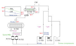
Figure 2. Spiral heat exchangers (H-701 and H-702) always are in service, as are two of three compressors (C-701, 702 and 703).
These compressors have run so smoothly that their simultaneous failure caught us by surprise. It took two days of frantic searching to find suitable oil filters.
Operations is wondering if we can continue to run the plant without refrigeration because the daytime high temperature now is about 30°F.
How do I resolve this puzzle? Can we safely operate the plant temporarily without ammonia refrigeration? Should we believe the ammonia flow calculation based on the condenser?
Send us your comments, suggestions or solutions for this question by March 12, 2021. We’ll include as many of them as possible in the April 2021 issue and all on ChemicalProcessing.com. Send visuals — a sketch is fine. E-mail us at [email protected] or mail to Process Puzzler, Chemical Processing, 1501 E. Woodfield Rd., Suite 400N, Schaumburg, IL 60173. Fax: (630) 467-1120. Please include your name, title, location and company affiliation in the response.
And, of course, if you have a process problem you’d like to pose to our readers, send it along and we’ll be pleased to consider it for publication.