Plant InSites: Upstream Heat Exchanger Configuration Demands Careful NPSH Analysis
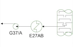
Consider the following scenario: Bubble point liquid leaves a distillation tower, passes through heat exchanger E27AB, enters centrifugal pump G37/A and continues to further processing. The pump feed configuration is shown in Figure 1. The net positive suction head available (NPSHavailable) should exceed the pump’s required NPSH by at least 1-3 feet to make pump operation reliable.
The NPSH available is found by: NPSHavailable = Psurface - Pvapor + ΔZ - hf - hv. Psurface is the pressure at the surface of the liquid; Pvapor is the vapor pressure of the liquid at the pump suction; ΔZ is the elevation change from the liquid surface to the centerline of the pump suction; hf is the frictional head loss through the system; and hv is the velocity head loss through the system. All the pressures and heads are in height of the flowing fluid.
Figure 1 is interesting because the tower is located above the pump suction (ΔZ is a large positive number), but the exchanger pressure drop, part of hf is also a large positive number. Will this system have sufficient NPSHavailable?
One other factor needs to be accounted for to evaluate this: If the pump suction temperature was the same as the tower temperature, Psurface = Pvapor and Psurface - Pvapor is 0. However, the exchanger E27AB cools the product draw, so Pvapor is lower than Psurface. This means Psurface - Pvapor is a positive number. The frictional loss in E27AB is offset by the combination of (Psurface - Pvapor) and the elevation change (ΔZ), not just by the elevation change.
In general, this configuration will typically work for hot systems assuming the exchanger pressure drop is low enough. In cold systems, heat gain from the environment also can be a factor and makes the analysis more complex.
Does the system work any better than having the pump upstream of the exchanger? For hydraulics, there is little difference. The downstream pressure after the pump and exchanger will be the same regardless of the configuration. Since the downstream pressure is the same and having the pump upstream of the exchanger gives a more straightforward and reliable NPSH, why have the exchanger upstream? The two most common reasons for this are exchanger pressure and pump seals.
The exchanger is at lower pressure when it is upstream of the pump. This may allow for reusing or purchasing an exchanger with a lower pressure rating than seen at the pump discharge. The lower pressure may also change safety relief contingencies for a leak.
Secondly, since E27AB cools the liquid, the pump feed liquid is colder if it is located after the exchanger. That may allow for selecting different pump seals or seal-system types.
Overall, Figure 1 with the exchanger upstream of the pump, is a much-less-common configuration that, as previously mentioned, has some advantages. But, in general, it doesn’t respond as well to increases in capacity as higher rates increase the pressure drop in E27AB and tend to decrease the temperature drop in the exchanger. Both reduce NPSHavailable at the same time and can lead to sudden onset of NPSH problems, with even small changes in rates.
The bottom line: Use this configuration if necessary, but remain aware of its limitations at high flow rates.
About the Author

Andrew Sloley, Plant InSites columnist
Contributing Editor
ANDREW SLOLEY is a Chemical Processing Contributing Editor.