Multiple Valves Cause Control Chaos

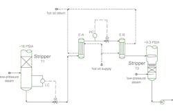
Recently, a chemical plant experienced level control problems on a stripper system. When a unit has operating or control problems, one feature that always grabs attention is two (or more) control valves in series. Figure 1 illustrates one such unit. The unit was having problems controlling the level in an upstream stripper (T1). At desired rates, the level would creep up until feed rates were dropped.
The process had two strippers in series (T1 and T2) with two hot oil exchangers heating the process between the strippers. The hot oil exchangers (E-A and E-B) were vertically mounted. The first had the process flowing up, the second had the process fluid flowing down.
The stripper had a level control valve on the bottoms flow from the stripper. High liquid levels would back up above the steam inlet. Once the liquid was above the steam inlet, the high velocity of the steam would throw liquid up into the packing, either damaging it or flooding the tower.
Downstream, a pressure control valve was on the bottoms flow as well. The pressure control objective was to control the pressure of the process at a point between E-A and E-B. The intent of the pressure control valve was to prevent excessive vaporization in exchanger E-A. The concern was that excessive vaporization would lead to reduced heat transfer due to vapor blanketing of the vaporizing surface in E-A [1].
The operating pressure of both strippers was tightly controlled. The T1 overhead pressure floated on a gas vent system that led to a thermal oxidizer. The thermal oxidizer released to atmosphere. Essentially, T1 pressure floated on atmospheric pressure. The downstream stripper (T2) overhead pressure was set by a variable speed motor attached to a vacuum pump. To meet process requirements, the T2 feed zone pressure was maintained tightly at 0.3 PSIA. The pressure constraints between T1 and T2 set a constant pressure drop of 15.7 PSI (16.0 PSIA minus 0.3 PSIA) between T1 and T2. This pressure drop did not change with flow rate variations.
The available pressure drop had to balance against elevation differences between T1 and T2, frictional losses in the piping and equipment (E-A and E-B), and the control valves for the T1 level controller and the E-A to E-B pressure controller. The pressure controller limited the total pressure drop available for the level controller. When the flow rate increased, the pressure drop through exchanger E-A rapidly increased. Each control valve had a minimum pressure drop related to the valve characteristics. Even when fully open, the valve sizing was such that the minimum pressure drops were a large percentage of the total available pressure drops.
While this system has complicated flow patterns, the system operates with a fixed and limited available pressure drop between T1 and T2. In such systems, even adding a small extra pressure drop can create unnecessary hydraulic limits. The two control valves in series cause such a pressure drop.
This system has other possible problems as well. The two control valves are in series with possibly competing control objectives. However you think about it, one process variable — flow rate — meets two control objectives: upstream level and intermediate pressure. This is a classic setup for control loops fighting each other and operating upsets.
One conceptual point can simplify thinking about multiple control valves in series. This simplification is from a process engineer’s rather than a control engineer’s perspective. Regardless of what they are called, all control valves are flow controllers. Here, the first valve is called an LC (or LCV), a level control valve. The second is a PC (or PCV), a pressure control valve. However, both modify flow rate. This is true for every control valve. They always change rates. The consequence is that some other variable changes due to the flow rate change, but the direct change is the flow rate. For mostly historical reasons, control valves have been given names for the type of secondary control they implement. This decision was much simpler to justify when control systems were built in pneumatic hardware. It’s much harder to justify in modern systems with software linkages. Nevertheless, control valve naming standards continue with the LCV, PCV and TCV in common usage.
Thinking about every control valve as a flow controller clearly highlights a possible problem with the control configuration. Of course, two flow controllers in series can fight each other! Thinking about the problem as a level control and a pressure control is not as self-evident to many. Level and pressure are different; why can’t you control them independently?
So, what was the solution here? Control valves have bypasses. The plant could either bypass the level controller or the pressure controller. The level controller is more critical here. Damage to the packing in T-1 would cause light material to end up in the T2 feed and overload T2’s vacuum system.
Set the PC valve open 100% and open the bypass around the PC between exchangers E-A and E-B, and see if the process works with only the level controller active. If sufficient duty is available in E-A and E-B, and other operating problems (such as vibration in two-phase flow) do not occur, stop worrying about vaporization in E-A. This was tried, and the unit worked fine. The final answer was to remove the PC valve completely.
If the test had not worked, the next step would have been to modify the hot oil supply temperature to prevent excessive vaporization in E-A. However, since the test worked, this was not required.
Conceptually, the plant layout had two clear problems with multiple control valves in series. The first is control problems related to valves fighting each other to meet competing objectives. The second is adding extra pressure drop to systems with tightly constrained hydraulics. Always running a mental check, thinking about every control valve being a flow controller, is one way to make these possible problems easier to find.
[1] SLOLEY, A. W., 2022. Consider Critical Heat Flux. Chemical Processing. October 2022. Vol. 84, no. 10, p. 33–34.
About the Author

Andrew Sloley, Plant InSites columnist
Contributing Editor
ANDREW SLOLEY is a Chemical Processing Contributing Editor.