Equipment Performance: Consider Critical Heat Flux
Having seen a similar problem before, my first question was about the cold side of the exchanger. “Was it a vaporizing service?” Indeed, it was. The next question was whether anyone had checked for critical heat flux limits on the vaporization. After a short silence, the response was “What’s critical heat flux?”
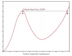
To understand what’s happening, we must go back to the 1930s. Shiro Nukiyama, a professor at Tohoku-Imperial University in Japan, was working on increasing the rate of vaporization and reducing the size of steam boilers. One limiting factor was called boiler burnout. During boiler heat-up, if the tubes got too hot, they would jump from a stable operating point generating steam to another operating point where the tubes would melt. Figure 1, which plots heat flux (duty/area) versus surface temperature superheat (temperature of the metal above the boiling point of the water), shows this jump. As a tube heated up, heat transfer rates increased along the curve to Point A. At Point A, the tube temperature suddenly would jump to Point B. (Often, the type of heat flux behavior depicted in Figure 1 is called a Nukiyama curve.) Unfortunately, for most boilers Point B exceeds the melting temperature of the tube metal.
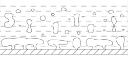
This problem had been known for a long time; parts of it were understood as early as the 1850s. However, Nukiyama was the first person to work out a full quantitative analysis. (While partial translations and abstracts were available, his full work was not translated into English until 1966.) He proposed that, at a certain critical heat flux (CHF) present at Point A, the vapor generated on the tube surface pushed liquid away from the tube so the tube surface no longer was fully wet. Figure 2 shows a general view of vapor pockets that occur at the CHF isolating part of the metal surface from liquid contact.
As the tube metal continues to heat up, the problem gets worse. Heat transfer drops even though temperature differences rise. At some point (the lowest heat flux between Point A and Point B shown in Figure 1), radiation heat transfer becomes significant and heat transfer starts to increase again. However, the operating region between Point A and Point B is not stable when heating up the boiler tube. Transition from Point A to Point B can occur exceptionally fast.
Predicting the CHF is an extremely complex problem. CHF values vary with physical properties of the fluid, operating conditions, flow conditions and geometry, surface characteristics, and other factors. Estimating the value is well beyond what we can discuss here. However, for most systems, CHF will lie below a 200°F surface temperature superheat. In fact, in some conditions, it may be as low as 72°F for boiling water.
The plant had moved from an average surface superheat temperature of just 150°F to nearly 400°F. The original exchanger configuration could suffer from vapor blanketing under some conditions. The new heat source only made the problem worse. Fortunately, the surface superheat temperature had not gone all the way up to Point B on the Nukiyama curve. The maximum temperature of the heat source wasn’t that hot. So, the large increase in hot temperature only achieved a small amount of extra duty.
Whenever you expect to run equipment far from current conditions, always check to make sure new factors in operation won’t prevent the desired performance. Extreme extrapolation often leads to many surprises.
About the Author

Andrew Sloley, Plant InSites columnist
Contributing Editor
ANDREW SLOLEY is a Chemical Processing Contributing Editor.