Reverse Osmosis Raises the Bar on Makeup Water Treatment
Key Highlights
- Reverse osmosis removes nearly all dissolved ions from makeup water, including chlorides, sulfates and silica that pass through sodium softening untouched, addressing impurities that increase blowdown, scaling and carryover risk in boilers.
- RO membranes require active protection against particulate fouling, scale formation and microbiological growth, using tools like cartridge filters, SDI and TOC testing, antiscalants,\ and biocide selection tailored to avoid chlorine attack on polyamide membranes.
- Performance monitoring depends on temperature-normalized metrics (normalized permeate flow and normalized salt rejection) to catch fouling or membrane damage early, with periodic offline cleaning triggered by defined thresholds in flow, pressure drop or salt rejection.
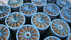
In the previous installment of this series, we examined a common and longstanding makeup water treatment method, ion-exchange sodium softening, for lower-pressure industrial boilers. But even when softening systems include a forced-draft decarbonator or other method to remove bicarbonate alkalinity, the remaining dissolved compounds, including chlorides, sulfates and silica, travel to the boiler. These impurities increase blowdown requirements, influence corrosion and scaling conditions in the steam generator, and increase the potential for impurity carryover to steam. Accordingly, we will examine the advantages of reverse-osmosis (RO) technology as a replacement for sodium softening. The key concept is that modern RO membranes can remove nearly 100% of the total ions from makeup water, far beyond the capabilities of softening.

The Reverse-Osmosis Evolution
RO emerged in the 1980s at utility power plants as pretreatment for existing ion exchange (IX) demineralizers. The development of synthetic ion-exchange resins early in the 20th century represented a quantum leap in the preparation of high-purity makeup water. However, even with “clean” supplies, such as a recreational lake or municipal potable water source, raw water normally contains enough dissolved ions to rapidly exhaust demineralizer resins. Resin regeneration is expensive, requires a waste-regenerant neutralization system and presents complexities related to hazardous chemical storage and handling. Retrofitting RO ahead of demineralizers greatly extended IX resin run times and lessened the impact of regeneration issues. RO has now become the leading demineralization technology for many combined-cycle heat recovery steam generators (HRSGs), with portable mixed-bed IX bottles or continuous electrodeionization (CEDI) for final polishing.
The UF-RO-IX design often serves as the core process for ultra-pure water preparation at other facilities, as well. Enhancements may include supplemental technologies, such as UV light chambers for microbial and organic compound destruction.
Successful power-plant applications of RO are trickling over (pardon the pun) to industrial plants with lower-pressure steam generators of 600 psi or less. While operating conditions are less severe in these units than in power boilers, impurities in makeup water can still be problematic if not properly controlled.
Fundamental RO Concepts
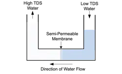
Osmosis is the natural process by which water flows across a semipermeable membrane from a dilute solution to a more concentrated solution, driving the two solutions toward equilibrium.
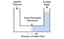
Osmosis imparts a differential pressure across the membrane. Logically, then, if an artificial pressure greater than the osmotic pressure is applied to the concentrated solution, purified water will be produced on the other side of the membrane. This is the basis of RO.
An RO built to the flat-sheet design shown in Figure 3 would take up an enormous amount of space, so the typical arrangement for industrial applications has each membrane wrapped with spacer and support material around a central, perforated tube, all placed in a cylindrical housing. These vessels are known as elements.
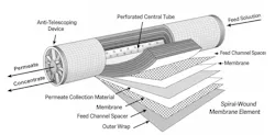
In this crossflow filtration process, applied pressure from the RO feed pump forces purified water through the membrane to the perforated central tube. The reject, aka concentrate, exits as a separate stream.
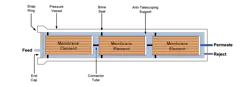
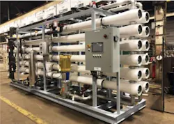
Standard spiral-wound element dimensions are 8 inches in diameter by 40 inches in length. Five or six membranes per pressure vessel is typical.1
Pump pressures of 100-200 psi are common for surface supplies, with higher pressures required for higher dissolved solids. Seawater desalination is the ultimate application for RO. Research continues on ways to improve membrane designs to enhance water flux rates and reduce feed pump pressures.
A basic RO flow schematic is shown below.

With normal surface waters as the supply, each stage will produce approximately 50% purified water (permeate) and 50% reject, for an overall recovery of 75%. The single-pass configuration is suitable for low-pressure steam generators, but note that for high-pressure steam generators and other high-purity applications, the two-pass RO design shown below is typical.

Two-pass RO is typical for the makeup treatment configuration outlined in Figure 1.
Protecting Reverse-Osmosis Membranes and Tracking Performance
We noted in Part 3 of this series that inadequate performance monitoring and maintenance of sodium softening systems have caused problems at numerous facilities over the years. RO monitoring and maintenance are equally important. The spiral-wound element configuration lends itself to particulate accumulation, scale formation and microbiological fouling without proper attention being given to pretreatment and internal water-treatment methods.
Particulate Fouling Control
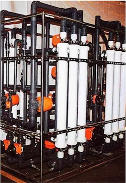
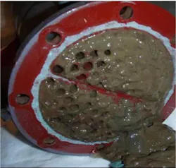
The tight fit between membranes and spacers offers an ideal location for particles to accumulate, especially in the lead elements. Thus, virtually every RO unit is equipped with a set of cartridge filters (5-25 µm, nominal pore size1) immediately upstream of the RO inlet. The cartridge filters capture fine particles, but they don’t have the capacity to serve as stand-alone filters. For years, clarification with effluent sand filtration was the common method for particulate removal, but micro- and ultrafiltration (MF and UF, respectively) have become popular for solids removal.2
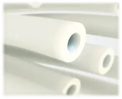
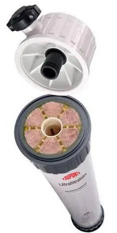
MF and UF are hollow-fiber membrane technologies, with the most common being the pressurized design, where each pressure vessel contains thousands of spaghetti-like membranes.
The process combines crossflow and dead-end filtration, in which many particles exit each vessel in a small waste stream, while some are captured within the membranes. Automatic, periodic off-line cleanings are necessary to prevent irreversible membrane fouling. Space limitations prevent further discussion of MF/UF now, but perhaps I can address the topic in a future Chemical Processing article.
The recommended measurement for calculating particulate fouling potential is the silt density index (SDI). SDI is a grab sampling test (which should be conducted regularly), in which a flowing sample is passed through a 0.45-µm filter at 30 psig. The test compares the time for 500 milliliters (mL) of water to pass through the filter at the beginning of the test (ti) and again after 15 minutes (tf).
The SDI is calculated as follows: SDI15 = (1-(ti/tf))/T x 100
As an example, consider the following data taken from an operating RO unit by the author:
ti = 34 seconds (s)
tf = 66 s
T = 15 minutes (min)
Per Equation 1, the SDI15 = 3.2
A general rule of thumb is that SDI should be below 5, preferably below 3, to protect RO membranes. However, low SDI values are not an absolute guarantee. Consider one case in which the SDI of the RO feed ranged from 1-3, but fouling from very fine iron oxide particles was problematic.
Some surface supplies contain significant concentrations of large organic compounds, such as tannins and humic acids, that can foul membrane surfaces. These compounds are normally measured as total organic carbon (TOC). A common recommendation is TOC <3 mg/L in RO feed. Activated carbon filtration may be needed as pretreatment for waters containing these compounds.
Scale Control
Protection against scale formation relies on accurate chemistry analyses and sampling over time to detect seasonal changes. While makeup systems at some plants have a sodium softener upstream of the RO to remove hardness, in many applications the RO feed enters with its initial ionic loading. A critical concept to remember is that even in the basic configuration shown in Figure 7, the dissolved solids concentration will increase fourfold from the beginning to the end of the process. Potential deposits, especially in the trailing membranes, include calcium carbonate (CaCO3), calcium sulfate (CaSO4), silica (SiO2) and hardness-silicate compounds. To this list can, at times, be added barium sulfate (BaSO4), strontium sulfate (SrSO4), calcium fluoride (CaF2), and calcium phosphate (Ca3(PO4)2). Reputable RO manufacturers and water-treatment chemical suppliers can supply the software to evaluate water chemistry and predict the scaling potential of many compounds. From this data, the correct antiscalant(s) and dosages can be calculated.
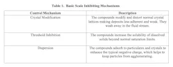
Polymeric inhibitors are common for scale control in RO membranes. The polymers contain active functional compounds, including phosphonic, carboxylic and sulfonic groups, which interact with scale-forming substances and inhibit scale formation through one or more of the mechanisms outlined in the table below.
The proper selection of an antiscalant program is highly dependent on accurate makeup water analyses that account for seasonal fluctuations.
Microbiological Fouling Control
Microbiological fouling can cause the most prompt and intense problems in plant water systems.
Accordingly, oxidizing biocide feed at the plant makeup water inlet is common for microbial control in the various water networks. However, residual oxidizing biocides, particularly chlorine, will attack RO membranes. The common membrane material is polyamide-based, a compound that contains nitrogen in the molecular structure. Chlorine bonds with nitrogen atoms and degrades the polymer. Activated carbon filtration or the feed of a reducing agent, such as sodium bisulfite, are methods to remove oxidizers. But some microbes will enter hibernation when exposed to an oxidizing biocide, then re-emerge and proliferate once the biocide is removed. These organisms can cause intense membrane fouling.
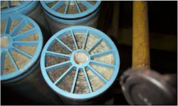
I personally handled several of these cases. One solution was to feed a non-oxidizing biocide immediately ahead of the RO cartridge filters to control re-emergent microbial colony formation. Another approach is to feed a mild oxidizing biocide, such as monochloramine (NH2Cl), to the RO inlet. The chlorine in this compound is already combined with nitrogen, but the chemical still has enough oxidizing power to kill microbes.
We will now consider performance-monitoring techniques to assist operators in maintaining proper conditions within an RO unit and to detect the onset of problematic conditions.
Performance Monitoring
Shown below are the common instruments and chemical feed locations for an RO unit.

These measurements are critical for monitoring RO performance and detecting fouling or scale formation. An important concept is that temperature significantly influences RO operation. As the temperature decreases, the channels within the membranes shrink, which reduces the flux rate. Conversely, warmer temperatures increase permeate flow and, to a small extent, salt passage. Temperature changes can mask fouling or scaling that, if allowed to progress too far, will cause irreversible damage. As outlined below, the instrument data must be “normalized” to accurately evaluate RO performance.
Normalized Permeate Flow (NPF): NPF algorithms collect temperature, pressure and flow data and compare current performance to baseline values, with temperature normalization. As membranes accumulate particulates or experience scale formation, feed and membrane pressure drop will increase, as evidenced by a decrease in NPF. A common rule of thumb suggests chemical cleaning at 10% NPF loss. A rise in NPF indicates membrane damage, such as oxidation or a mechanical issue. Permeate-specific conductivity also should rise in these cases. A feature that can be highly valuable in troubleshooting mechanical leaks is the use of a grab-sample port on each permeate-discharge line. Then, if the overall permeate conductivity meter readings rise, an operator can check each pressure vessel and narrow down the problem location.
Normalized Salt Rejection (NSR): NSR compares salt rejection during current operation to start-up conditions, with influencing factors being temperature and net driving pressure. An NSR decrease indicates membrane damage, perhaps from oxidation or scale formation. The data also can be calculated as normalized salt passage, which equals 1 - NSR. Both calculations work well for troubleshooting.
Modern monitoring/control systems allow data to be displayed in real time, giving operators and technical personnel a heads-up on system performance and upset conditions.
RO Element Cleaning
Even with well-designed pre- and process-treatment programs, RO membranes gradually accumulate suspended and dissolved solids. If not removed, the solids will eventually cause irreversible fouling. Accordingly, periodic off-line cleanings are necessary to restore membrane conditions to near baseline. Recommended guidelines to initiate a cleaning are:1
- Loss of 10%-15% in normalized permeate flow
- Increase of 10%-15% in normalized differential pressure
- Decrease of 1%-2% in salt rejection
Because fouling occurs on the concentrate side of the membranes, cleaning solutions are delivered through the reject circuit. Piping and connections should be plumbed such that each stage can be cleaned individually with a fresh cleaning solution. Figure 14 illustrates the basic schematic of a cleaning skid.
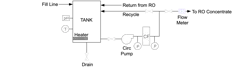
RO permeate is a requirement for cleaning-solution makeup. Via the recycle line and tank heater, the solution is brought to an appropriate temperature range (95°-105°F is common). The operators then valve in the circulation loop to and from each stage. A standard component of the circuit is a cartridge filter (CF on the diagram) to capture particles released during cleaning. Both acidic and alkaline solutions may be necessary for cleaning to remove mineral scales, organic compounds and other materials. With the aid of feed-water chemistry and operating data, a reputable RO equipment or membrane supplier should be able to recommend and/or provide formulations for optimal cleaning. Modern RO membranes can handle a relatively broad pH range, but expert advice is important for optimizing cleaning solutions.
A Cautionary Note
Somewhat regularly, I see comments in literature or on LinkedIn about RO permeate being “hungry” water and that metal ions will leach from metal piping, most notably carbon steel, because the water has few ions. But what some of these authors seem to forget is that highly purified water has been used as makeup for power plant boilers for nearly a century. The key is proper chemical treatment to keep the metals in a passive state. Impurities from leaking heat exchangers or other sources can override the benefits of a well-operated makeup water treatment system.
Conclusion
Reverse osmosis offers a more complete solution to makeup water treatment than sodium softening. The downstream benefits can be quite substantial. But RO units require conscientious monitoring and control. For readers considering this technology for softener replacement or as the makeup method for new plants, comprehensive raw-water chemistry analyses are necessary for proper system design. These include analyses over time to determine seasonal effects on chemistry. Systems designed from a snapshot or incomplete analysis often fail shortly after startup.
Disclaimer
This article offers general information and should not serve as a design specification. Every project has unique aspects that must be individually evaluated by experts from reputable water treatment equipment firms.
References
- Byrne, W., Reverse Osmosis: A Practical Guide for Industrial Users, Tall Oaks Publishing, Littleton, Colorado, 2002.
- Buecker, B., “Microfiltration: An Up-and-Coming Approach to Pre-Treatment for the Power Industry”; from the proceedings of the 26th Annual Electric Utility Chemistry Workshop, May 9-11, 2006, Champaign, Illinois.
- Buecker, B., and Post, R., Improve Your Cooling Tower Treatment | Chemical Processing | Chemical Processing
About the Author
 Brad Buecker, SAMCO Technologies
Brad Buecker, SAMCO Technologies
Brad Buecker currently serves as Senior Technical Consultant with SAMCO Technologies. Buecker has many years of experience in or supporting the power industry, much of it in steam generation chemistry, water treatment, air quality control, and results engineering positions with City Water, Light & Power (Springfield, Illinois) and Kansas City Power & Light Company's (now Evergy) La Cygne, Kansas, station. Additionally, his background includes eleven years with two engineering firms, Burns & McDonnell and Kiewit, and he spent two years as acting water/wastewater supervisor at a chemical plant. Buecker has a B.S. in chemistry from Iowa State University with additional course work in fluid mechanics, energy and materials balances, and advanced inorganic chemistry. He has authored or co-authored over 300 articles for various technical trade magazines, and he has written three books on power plant chemistry and air pollution control. He is a member of the ACS, AIChE, AMPP, ASME, AWT, and he is active with Power-Gen International, the Electric Utility & Cogeneration Chemistry Workshop (now co-located with the POWERGEN conference), and the International Water Conference. He can be reached at [email protected].