Sodium Softening: The Workhorse of Industrial Boiler Makeup Water Treatment
Key Highlights
- Countercurrent regeneration systems improve efficiency by reducing regenerant use and minimizing residual impurities.
- Monitoring softener performance is vital to prevent boiler tube deposits and maintain operational efficiency.
- Alkalinity removal is essential to prevent carbonic acid formation, which can cause corrosion in condensate return piping.
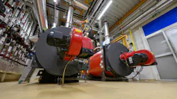
The modern water-tube steam boiler design emerged in the mid-1800s in large part from efforts by pioneers such as George Babcock and Stephen Wilcox. (You may recognize these two inventors as the B&W of the boiler company that is still going strong today.) Prior to the late 1800s, steam was mainly a heating source and an industrial tool.1 When utility companies formed in the early 20th century, they turned to steam for electric power generation and distribution to serve industrial and residential users across wide areas.1 This led to rapid growth in boiler size, pressure and temperature, and the construction of the large coal-fired boilers by mid-century. The increasing sophistication and designs for greater temperatures and pressures required higher purity makeup. A quantum leap in this regard came with the development of synthetic ion-exchange resins in the 1930s.
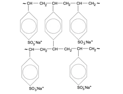
The most common resin structure is polystyrene cross-linked with divinylbenzene. Figure 2 shows a snippet of the molecular schematic for sodium softening resin.
Sodium softening became, and remains, common for steam generators operating under conditions shown in Table 1 below. The table is from the recent revision of the American Society of Mechanical Engineers (ASME) industrial boiler water guidelines.2 (The complete guidelines are available from the ASME and should be in the library of any industrial plant with steam generators.)
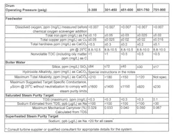
As the table indicates, moderate impurity levels are allowable for low- and medium-pressure units, but the limits become stricter with increasing pressure. A key point to note is the low feedwater hardness concentration for all applications. Enter the sodium softener.
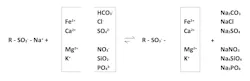
As the service water influent passes through the softener bed, the following exchange reactions occur.
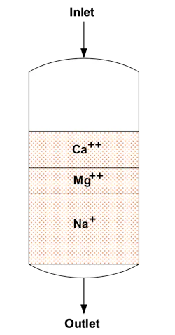
The resin exhibits ion selectivity, as shown for hardness in Figure 6.
The layers expand in depth during operation, and if the bed is allowed to reach complete exhaustion, hardness will begin to appear in the effluent. I once worked at a chemical plant where a critical process relied on sodium softened water. Even minor calcium concentrations would impact the manufacturing process, so we installed an on-line, continuous calcium monitor on the softener effluent line to immediately alert the water treatment staff of upset conditions. Standard operating guidelines called for operation to a throughput volume that reasonably approached but did not threaten bed exhaustion. The continuous monitor provided an extra layer of protection.
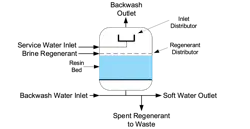
Softener Regeneration
Per the reaction arrows shown in Figure 5 and the stratification zones in Figure 6, the resin’s active sites have a much stronger affinity for other cations, and especially multivalent cations such as Ca2+ and Mg2+, than sodium. Ion exchange is an equilibrium reaction, which, during normal operation, is oriented strongly to the right. In accordance with Le Chatelier’s Principle, treatment of the resin with a concentrated brine solution is needed to drive the reaction to the left and remove accumulated hardness and other ions. These exit with the waste regenerant stream. The following steps outline the overall regeneration process.
Backwash
A resin bed is excellent at filtering particulates and will collect suspended solids that escape the pretreatment systems. Also, some resin degradation occurs during normal operations that generate resin “fines.” These materials restrict flow and reduce unit efficiency. Backwash is the first step. Counter-current backwash design is typical. Common guidelines target 40% to 50% bed expansion during backwash,3 so the vessel must be designed with open volume (known as freeboard) at the top to allow this expansion. The backwash flow rate must be adjusted for water temperature, as water density increases with decreasing temperature, and without adjustments, some of the resin may exit the softener during cold-water backwashes. Recommended backwash flow rates are normally provided by the resin manufacturer. Regarding backwash duration, 10-15 minutes is typically sufficient, though some extreme cases may require 20-30 minutes.3
Brine Injection
Brine regenerant solutions are usually prepared in an external tank with high-purity, softener-grade rock salt. The maximum salt solubility at 20°C is around 26% by weight, but this is normally diluted to 8% to 12% for regeneration, as higher concentrations can cause osmotic shock to the resin that breaks down the beads. A common ratio is 6 lbs. of salt per cubic foot of resin, with 30-minute regenerations.3
Slow Rinse
Following regeneration, residual brine must be removed from the resin to prevent contamination of the makeup upon return to normal operation. The slow rinse, at regeneration flow rates but without the brine, allows the remaining brine in the resin to continue regeneration as it moves through the bed. Total flow of one to three bed volumes is common for the slow rinse step.
Fast Rinse
The fast rinse, at service water flow rate, expeditiously prepares the resin for return to service. Like the spent regenerant and slow rinse volume, the fast rinse effluent is diverted to a drain. The effluent should not be switched to service until the water quality reaches acceptable limits. Online conductivity is commonly used to evaluate rinse completion and unit return. Grab sample or online hardness testing is an additional method for verifying the efficacy of the rinse process.
A Note About Countercurrent Regeneration
Figure 3 illustrates a co-current softener, in which the regenerant follows the same path as the service water. Thus, during regeneration, hardness and other exchanged ions flow through the full bed, detaching and reattaching along resin sites. A major design change that has been available for years and is quite common in high-purity demineralizers is countercurrent regeneration. The system is plumbed such that the regenerant solution flows in the opposite direction of the service water. The unwanted cations do not have to pass through the full bed during the regeneration step, which lowers the amount of regenerant needed, reduces the rinse times and significantly reduces leakage of residual impurities into the service stream.
Countercurrent systems depend on the ability to regenerate the resin while it remains in a compacted state, and numerous mechanical approaches have been engineered to achieve this. Solutions include:
- A blocking flow of water moving from the top of the unit to a takeoff distributor located at the top of the resin bed. The distributor removes the upflow regenerant solution. The blocking flow prevents the bed from expanding beyond the takeoff distributor.
- A buried takeoff distributor below the top surface of the resin bed.
- Reversing the service flow to go from top to bottom and at sufficient velocity to keep the resin compacted against a top distributor. Regeneration is then downward as the resin comes to rest and compacts against the bottom distributor.3
Alkalinity Removal
Referring again to Table 1, it’s evident that alkalinity, including bicarbonate (HCO3-) and perhaps a bit of carbonate (CO32-) alkalinity is allowed in low- and medium-pressure boilers. However, most of this alkalinity, when heated in the boiler, will decompose to carbon dioxide.

Carbon dioxide escapes with steam and then re-dissolves in condensate to generate carbonic acid (H2CO3). Accordingly, many industrial steam generator makeup systems include some method of decarbonation. A common example is shown below.
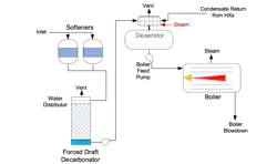
CO2 removal can be enhanced by acid feed upstream of the decarbonator with caustic feed downstream to re-adjust the pH. This arrangement adds a bit of complexity to treatment control.
We will return to the issue of carbonic acid corrosion of condensate return piping in a later installment.
Don’t Neglect Softener Performance Monitoring and Maintenance
Based on my experience, plant managers and industrial operators often neglect water or steam chemistry because they’re overly focused on process chemistry and engineering. The same is also often true with the treatment of cooling water, which I covered in a previous series for Chemical Processing.5 A common issue is periodic resin exhaustion or other operating problems that allow hardness leakage, which in turn generates hardness-based deposits in boiler tubes.
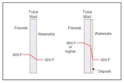
Of course, such deposits inhibit heat transfer that greatly reduce boiler efficiency and can cause boiler tube failures due to overheating.
It is the latter problem that usually induces plant management to contact water treatment experts to investigate the cause of the failures. The first place to start in an investigation is the softener operating log in search of unit upsets. Some cases are known where, when a softener malfunctioned, management ordered the water treatment staff to bypass the softener and feed raw water to the boiler(s). Severe tube failures were the result. I discussed this topic with Chemical Processing Editor-in-Chief Traci Purdum in a recent podcast.7
To Be Continued
A key point in this discussion is that sodium softeners, when properly operated and maintained, will reduce hardness ions, typically the two most troublesome ions in boiler makeup. A decarbonator will also remove most bicarbonate alkalinity. However, the other ions remain. These compounds can increase boiler blowdown requirements and lead to other deposits or corrosion. Reverse osmosis (RO), which became quite popular as the lead unit(s) in power plant demineralization systems, continues to gain attention as a primary demineralizer for industrial boilers. RO fundamentals will be covered in Part 4 of this series.
Disclaimer
This article offers general information and should not serve as a design specification. Every project has unique aspects that must be individually evaluated by experts from reputable water treatment equipment firms.
References
- Kitto, J.B., and Stultz, S.C., Eds., Steam, its generation and use, Edition 41, the Babcock & Wilcox Company, Barberton, Ohio, 2005. Figure 10, Chapter 2, Page 2-18.
- “Consensus on Operating Practices for the Control of Feedwater and Boiler Water Chemistry in Industrial and Institutional Boilers”; American Society of Mechanical Engineers, New York, NY, 2021.
- Owens, D.L., Practical Principles of Ion Exchange Water Treatment; Tall Oaks Publishing, Littleton, Colorado, 1995.
- Dowex Upcore vs. Advanced Amberpack: What’s the Difference? - SAMCO Technologies
- Buecker, B., “Cooling Tower Series, Parts 1-6”; Chemical Processing, September 2024-March 2026.
- Buecker, B., and Shulder, S., “Combined Cycle and Cogeneration Water/Steam Chemistry Control”; pre-workshop seminar of the 40th Annual Electric Utility Chemistry Workshop, Champaign, Illinois, June 7, 2022.
- “Water Is Water — And Other Costly Myths” | Chemical Processing
About the Author

Brad Buecker, SAMCO Technologies, Buecker & Associates, LLC
President, Buecker & Associates, LLC
Brad Buecker currently serves as Senior Technical Consultant with SAMCO Technologies. Buecker has many years of experience in or supporting the power industry, much of it in steam generation chemistry, water treatment, air quality control, and results engineering positions with City Water, Light & Power (Springfield, Illinois) and Kansas City Power & Light Company's (now Evergy) La Cygne, Kansas, station. Additionally, his background includes 11 years with two engineering firms, Burns & McDonnell and Kiewit, and he spent two years as acting water/wastewater supervisor at a chemical plant. Buecker has a B.S. in chemistry from Iowa State University with additional coursework in fluid mechanics, energy and materials balances, and advanced inorganic chemistry. He has authored or co-authored over 300 articles for various technical trade magazines, and he has written three books on power plant chemistry and air pollution control. He is a member of the ACS, AIChE, AMPP, ASME, AWT, and he is active with Power-Gen International, the Electric Utility & Cogeneration Chemistry Workshop, and the International Water Conference. He can be reached at [email protected].