Makeup Water Treatment Series Part 2: The Case for Comprehensive Raw Water Analysis
Key Highlights
- Microfiltration and ultrafiltration have emerged as effective pretreatment technologies, capable of removing much smaller particles than traditional clarifiers.
- Accurate raw water analysis is critical for system design, especially to handle fluctuations in suspended solids, flow rates, and chemistry.
- Case studies demonstrate that replacing clarifiers with microfilters can dramatically improve turbidity removal and extend maintenance intervals.

Early clarifier designs typically had a large volume and accompanying footprint to provide the needed residence time for particles to agglomerate and reach the proper settling mass. Rise rates in these units were generally within a range of 0.5-1.5 gpm/ft2. Rise rate is the ratio of effluent flow (gallons-per-minute) to the surface area at the top of the clarifier. Industry research has focused on ways to improve clarifier efficiency and reduce size. The inclusion of inclined plates into clarifier design became a major feature for many units.
The key aspect of the lamella design is that coagulated/flocculated solids must flow upwards along the plates, a process that enhances particle agglomeration and settling. This allows a significant increase in water rise rate and corresponding decrease in unit size and footprint. Advancements have also been made in solids contact clarifier design. This process utilizes mature coagulated/flocculated solids or sometimes even supplementary addition of solid particles to the clarifier to enhance collection of newly formed flocs.
Standard for clarifiers is gravity sand or multimedia filtration to collect particulates that may escape with the clarifier effluent. For any new system, accurate calculation of filter capacity, and hydraulic loading is an important part of the process design.
A note about softening clarifiers
Some groundwater sources may contain high concentrations of one or more dissolved solids, including calcium, magnesium, bicarbonate alkalinity, iron, manganese, silica and other scale-forming or fouling compounds. Lime softening clarification may be necessary to reduce the levels of these compounds upstream of specialty water-treatment equipment, such as reverse osmosis (RO) and ion-exchange (IX) units. We will discuss lime softening in a follow-up article.
But before reviewing newer technologies, which are often replacing clarifiers for suspended solids removal, it’s worth mentioning the importance of accurate raw water analyses when designing any system.
Upfront Raw Water Analyses
A critical aspect when selecting and sizing any makeup water-treatment system is obtaining comprehensive raw water chemistry data. My colleagues and I have seen too many cases in which the system design was based on a snapshot or only partially complete water analyses. When placed in operation, the units sometimes performed poorly and, in a few cases, had to be replaced. Regarding clarifier systems, Reference 1 outlines several primary issues that most influence unit design and operation. Four of these are summarized below.
- Suspended solids fluctuations: For surface waters, in particular, long-term climate fluctuations and near-term weather events can greatly influence suspended solids concentration. The most dramatic examples come from rivers in locations with substantial topsoil. After a heavy rainstorm, turbidities may rise from single-digit nephelometric turbidity units (NTU) levels to readings in the hundreds or even thousands. The rapid increase in suspended solids can overwhelm pretreatment equipment. Remedies include designing systems with redundancy, modernizing chemical feed controls and ensuring that the sludge-removal system can handle the increased load. For many facilities with surface supplies, large solids, most notably tree branches and other vegetation, may be problematic and require inlet screens to keep the debris from reaching clarifiers or other specialized equipment.
- Flow variations: Flow requirements within a plant may vary significantly. Accurate calculation of peak demand allows for pretreatment design flexibility to handle max flow but also off-peak conditions. Answers include redundant equipment and strategic placement of surge tanks.
- Variable inlet chemistry: Apart from suspended solids issues, surface water chemistry can also fluctuate appreciably due to weather influences and seasonal effects. Some changes, such as an increase in dissolved solids concentration, may not severely influence clarifier operation but can cause scaling and fouling in downstream equipment like reverse-osmosis (RO) systems. While groundwater supplies often have stable chemistry, the water may contain significant concentrations of hardness, alkalinity, dissolved iron and manganese and other compounds. Removal of dissolved ions and molecules may require enhanced treatment, perhaps even lime softening clarification.
- Sludge disposal: Not to be overlooked is disposal of sludge and wastewater generated by industrial equipment and processes. It’s imperative to coordinate with the proper environmental authorities to understand the chemistry limits for all discharge streams and then design the treatment systems accordingly. Often, some streams can be combined internally to reduce the number of discharge points. In the U.S., discharge limits fall under the National Pollutant Discharge Elimination System (NPDES) guidelines, but individual states have the freedom to implement other limits as they so deem. Common core NPDES parameters are pH, suspended solids, oil and grease and total dissolved solids. But given the nature of industrial processes and the potential for impurity leakage to wastewater streams, other items may include heavy metals, organic compounds and biological nutrients, such as phosphate and nitrogen species.
A key takeaway: Water treatment in industrial plants must be viewed holistically due to the potential influence of each process on others.
The Emergence of MF and UF for Suspended Solids Removal
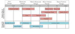
The last two decades have seen the rapid emergence of micro- and ultrafiltration (NF and UF, respectively) as alternatives to clarification for many pretreatment applications. Figure 3 outlines particulate size ranges for common filtration technologies.
RO and nanofiltration (NF) are for ionic solids removal only. The processes typically utilize spiral-wound membranes and require the pretreatment we have been discussing here and in Part 1 because suspended solids can cause prompt and serious fouling.
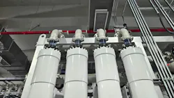
As Figure 3 indicates, MF, and especially UF, can remove much smaller particles than clarification-filtration. The most common designs have pressure vessels operating in parallel.
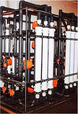
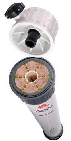
Each pressure vessel is filled with thousands of spaghetti-like hollow fiber membranes (Figure 5a and 5b).
The process operates via a combination of crossflow and dead-end filtration in which the raw water flows parallel to the membrane surfaces. Water continually passes through the membranes on its flow through each pressure vessel, but many particles remain in the small reject stream that exits the vessels.
Both outside-in and inside-out permeate flow paths are possible, though the outside-in process seems to be more common. Even though UF can remove very fine particles, pore sizes are still much larger than those in RO membranes, so corresponding inlet pressures and feed pump requirements are much lower than for RO.

Some particulates continually collect in the membranes, and this debris must be periodically removed via an air enhanced backwash process. A representative cycling time might be 20 minutes of water production followed by a one-minute air scrub/reverse flush step to remove embedded solids.
Modern units include regular chemically enhanced backwashes, where after a set number of cycles, a chemical(s) is injected into the backwash water to help clean out debris. Citric acid is common for removal of iron-oxide particles, while caustic and bleach will attack organics and microbiological deposits. We will return to the microbial issue shortly.
The following case history outlines a real-world example of clarifier replacement and subsequent operation of a microfiltration unit.
Case History: A Real-World Pretreatment Upgrade That Delivered Results
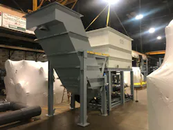
In the mid-2000s, I served as lead on a project to replace an aging clarifier with a microfilter at my second former power plant. The high-purity makeup configuration just before the changeout is shown in Figure 6.

It proved to be a straightforward task for the plant’s maintenance staff to set the MF in place, disconnect the inlet line to the clarifier and the outlet line from the media filters, and, with temporary hoses, plumb the MF for full-scale testing. Prior to the replacement project, the clarifier/filter effluent turbidity typically ranged between 0.3-1.0 NTU. This equated to three-week intervals between needed replacements of the RO cartridge filters, as determined by differential pressure readings.
Upon MF startup, effluent turbidity levels dropped to less than 0.05 NTU and remained at that level. The RO cartridge filter replacement interval increased from three weeks to three months, another indicator of much improved pretreatment particulate removal. The results were so positive that plant management authorized permanent installation of the equipment and within two years replaced the clarifier on the second power unit’s makeup water train with a microfilter.

This example and others like it have led to a significant transformation in pretreatment for high-purity makeup water systems, at least in the power industry. Figure 7 illustrates this evolution.
Apart from renewable energy production methods, e.g., wind and solar, combined cycle power generation has been the major replacement for the many coal-fired plants that are now retired. The scheme shown above is a popular arrangement for high-purity makeup to the heat recovery steam generators (HRSGs) of combined cycle units. An added benefit of this configuration is the use of portable mixed-bed ion exchange bottles that a contractor can swap out when IX resin exhausts, eliminating the need for plant personnel to regenerate resin on site.
Protecting MF and UF Systems
During initial operation of the unit outlined above, we began to realize that the microfilter required periodic (every two to three months) off-line cleanings to remove debris that the automatic backwash cycles did not.
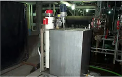
The cleaning process that evolved was a stepwise procedure of, first, treatment with a warm (100°F), dilute sodium hydroxide (1%) and sodium hypochlorite (500 mg/L) solution, a rinse with filtered water and then cleaning with a warm citric acid solution (0.5%), followed by another rinse. Cleaning took approximately eight hours, or one work shift. The plant maintenance staff fabricated the wheeled cart shown in Figure 8, which included a mixing tank, mixer, hose connections and Chromalox heater.
The cart also proved quite valuable for cleaning auxiliary heat exchangers during unit outages, as it could be easily moved to many locations in this large power plant.
One Last Item
One last critical point of discussion for this installment: The basic schematic in Figure 6 does not show coagulant and flocculant feed lines to the clarifier, but these can always be assumed for systems of this type. However, the figure does include oxidizing biocide feed, in this case bleach. Water systems of all types serve as potentially fantastic breeding grounds for microbes. The two pretreatment systems at this plant had bleach feed upstream of the clarifiers to protect the piping and equipment from microbiological fouling. We left these feed systems in place, as MF and UF membranes are typically quite robust and can handle continuous oxidizer feed. However, as I will highlight in the next installment, oxidizers attack RO membranes, most notably chlorine. The next article in this installment will address ways to protect RO membranes.
Disclaimer
This article offers general information and should not serve as a design specification. Every project has unique aspects that must be individually evaluated by experts from reputable water treatment firms.
References
- “The Fundamentals of Raw Water Treatment”; www.samcotech.com.
About the Author

Brad Buecker, SAMCO Technologies, Buecker & Associates, LLC
President, Buecker & Associates, LLC
Brad Buecker currently serves as Senior Technical Consultant with SAMCO Technologies. Buecker has many years of experience in or supporting the power industry, much of it in steam generation chemistry, water treatment, air quality control, and results engineering positions with City Water, Light & Power (Springfield, Illinois) and Kansas City Power & Light Company's (now Evergy) La Cygne, Kansas, station. Additionally, his background includes 11 years with two engineering firms, Burns & McDonnell and Kiewit, and he spent two years as acting water/wastewater supervisor at a chemical plant. Buecker has a B.S. in chemistry from Iowa State University with additional coursework in fluid mechanics, energy and materials balances, and advanced inorganic chemistry. He has authored or co-authored over 300 articles for various technical trade magazines, and he has written three books on power plant chemistry and air pollution control. He is a member of the ACS, AIChE, AMPP, ASME, AWT, and he is active with Power-Gen International, the Electric Utility & Cogeneration Chemistry Workshop, and the International Water Conference. He can be reached at [email protected].