Reduce Time Delay in Your Analytical System
Process measurements are instantaneous but analyzer responses never are. There's always a time delay from tap to analyzer. Unfortunately, this delay, which represents the time a sample takes to reach the analyzer, often is underestimated or misunderstood.
Using a regulator is one way to address time delay. Regulators control pressure, which in an analytical system closely correlates with time. For gas systems with a controlled flow rate, the lower the pressure, the shorter the time delay.
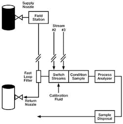
Delay may occur in any of an analytical instrumentation system's major parts, including the process line, tap and probe, field station, transport line, sample conditioner, stream switching system and analyzer (Figure 1).
Time delay is cumulative. It consists of the total amount of time fluid takes to travel from the latest step in the process line to the analyzer, including time required for analysis in the instrument.
Here, we'll focus on the field station and the regulator's important role in reducing time delay there.
Initial Steps
Minimizing time delay begins with proper tap location. It's best to place the tap as close to the analyzer as possible and upstream of sources of delay such as drums, tanks, dead legs, stagnant lines and redundant or obsolete equipment.
In many cases you can't dictate tap location. You may have to make do with an existing spot and, often, with the current analyzer shed position as well.
If the tap is far from the analyzer, use a fast loop to quickly deliver fluid to the analyzer and return the unused portion to the process.
When dealing with a liquid, ensure pressure at the tap suffices to deliver the sample through transport lines or fast loop without a pump, which is expensive and introduces performance variables.
In most systems the probe contributes to time delay — the larger the probe's volume, the greater the delay. So, choose a low-volume probe.
Using a Regulator
Regulators don't suit all systems. For an analyzer requiring a liquid sample it's better to keep the liquid at high pressure to avoid formation of bubbles.
For gas samples use a regulator in a field station to reduce pressure in transport lines. Time delay decreases in direct proportion to absolute pressure — halving pressure halves time delay.
Locate the field station as close to the tap as possible. The sooner the pressure is dropped, the better.
Let's look at three possible regulator applications. Each requires a somewhat different configuration.
In the first application the objective is to reduce gas pressure and pressure drop isn't expected to produce condensation. A simple pressure-reducing regulator will suffice.
This regulator maintains constant pressure at the outlet. A thin metal diaphragm within the unit flexes in response to downstream pressure, allowing a cone-shaped poppet to regulate the size of the orifice through which gas passes. Higher pressure causes the diaphragm to flex up, making the opening smaller. Lower pressure lets the diaphragm relax, enlarging the opening. A dial (handle) on the regulator allows the operator to set outlet pressure.
A metal diaphragm is ideal in applications where inlet pressure doesn't vary sharply. However, where pressure may become erratic or spike, consider a piston-style regulator.
In our second application the objective also is to reduce gas pressure but pressure drop is expected to produce condensation. With a drop in pressure almost all gases lose heat via the Joule-Thomson effect. If the gas is close to its dew point this cooling may result in condensation. In some cases heat loss may be great enough to cause the regulator to freeze up.
When the Joule-Thomson effect is in play you may need a heated regulator to keep gas temperature above the dew point. A heated regulator is a pressure-reducing regulator in which system fluid flows over a heated element. A heater cartridge is required.
To ensure buying a heater cartridge in the right power range, calculate the number of watts required (Pw) via:
Pw = Qn Cp ΔT
where Qn is molar flow, Cp is heat capacity of the fluid and ΔT is Joule-Thompson coefficient or the amount of cooling from the Joule-Thomson effect for the particular gas.
In our third regulator application you must vaporize a liquid before it can be sent to a gas chromatograph or other analyzer. This calls for a vaporizing regulator.
The objective of a vaporizing regulator is to instantly flash the entire sample. This requires applying a lot of heat at the precise location of the pressure drop.
Vaporizing regulators are tricky but, if properly sized and installed, can reliably prepare a liquid sample for a gas analyzer.
You must pay close attention to flow. Too great a flow will lead to partial vaporization and liquids passing through the regulator toward the analyzer. Too little flow will prompt vaporization of the liquid sample upstream.
Failure to correctly set up your vaporizing regulator can create considerable time delay. As fluid changes from liquid to gas, volume dramatically increases. The rate of increase depends upon the liquid's molecular weight.
Typically, measured vapor flow after the regulator will exceed liquid flow before the regulator by more than 300 times. For example, a vapor flow of 600 cm3/min may stem from liquid flow of less than 2 cm3/min. Therefore, the liquid will take 25 minutes to travel through 3 m (approximately 10 ft) of 6-mm (¼-in.) tubing. To decrease this time, you must reduce the volume of tubing preceding the regulator. For example, with only 1 ft of 1/8-in. tubing, liquid would reach the regulator in only 30 sec. However, you must add to that time delay in the probe — the narrower the probe, the faster the response.
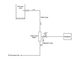
Another way to attain a faster response is to move the regulator closer to the analyzer with the aid of a second fast loop. Figure 2 shows the regulator located after the fast loop filter with a second liquid fast loop ensuring good liquid flow continues right to the vaporizing regulator. The objective is to minimize slow-moving liquid volume going to a vaporizing regulator.
Tackle Time Delays
A regulator is a critical tool in addressing time delay in an analytical system. By reducing pressure, you reduce the delay. The lower the pressure in a gas system, the faster the response time. In general, the sooner system pressure can be dropped, the better.
Where liquid must be vaporized, make intelligent use of fast loops to keep the liquid moving right up to the vaporizing regulator.
The field station is one place in a complex analytical system where you can significantly reduce time delay. However, this requires a comprehensive approach that scrutinizes all potential causes of delay in the system.
DOUG NORDSTROM is market manager, analytical instrumentation, for Swagelok Co., Solon, Ohio. MIKE ADKINS is general industrial valve product manager for Swagelok in Solon. E-mail them at [email protected] and [email protected].