Piping Tips: Use Your Head With Headers

Many flow systems use manifolds or headers to distribute fluid to multiple paths. Such arrangements often arise with heat exchangers, centrifuges, reactors and other equipment. Usually, the aim is to send the same amount of fluid through each path. Then, after passing through the equipment, the flow recombines.
In some systems, e.g., many of those for fired heaters, keeping flow rates equal is so important that each flow pass has a control valve or other device, such as a critical flow nozzle, to ensure even flow rates. In others, the inherent configuration of the piping and equipment sets the flow allocation.
Figure 1 shows two generic ways for flow splitting and combining using inherent piping and equipment configuration. The bifurcation splitting approach attempts to ensure the same flow rates by having a truly symmetric piping network. This may work if the number of splits is 2N — but configurations with a different number of splits are not truly symmetrical. Additionally, symmetric splitting tends to be very expensive because it requires a lot of pipe and fittings if a large number of splits is needed.
Consecutive splitting is a simpler and cheaper alternative. For splitting, multiple branches come out of a common line. For combining, multiple branches enter a common line. Figure 1 depicts two major options. In the U-type or reverse flow configuration, the first flow split off is the last flow combined. In the Z-type or parallel flow configuration, the first flow split off is the first flow combined.
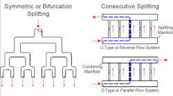
Figure 1. The U-type configuration provides more-even flow distribution.
Depending upon the situation, the performance of the U-type and Z-type may vary considerably. For convenience, the inlet header often uses a single diameter. With a constant-diameter main header, at each flow split the velocity in the main header drops, per the Bernoulli equation:
P + ½ mV 2 + ρgH = K
where P is pressure, m is mass, V is velocity, ρ is density, g is the gravitational constant, H is height, and K is a constant.
Thus, when velocity drops in the splitting manifold, something else must change. For a simple system, ρ, g and H do not change, so P must. As velocity decreases in the main header, the static pressure increases. In the combining manifold, the opposite occurs. As each flow enters the manifold, the velocity rises and the pressure falls.
When every flow path between the headers is identical, varying pressure drop across the flow paths causes flow rate changes. For the U-type header, the lowest inlet pressure is at the first split. The first split, as the last to join the collection header, also has the lowest outlet pressure. These pressure variations can create flow distribution problems.
The Z-type header also has the lowest pressure at the first split. However, by also joining the combining header first, that split results in higher outlet pressure and, thus, a larger variation in flow rates than in a U-type header.
Now, if the pressure drop in each parallel path is very high compared to pressure recovery-loss due to velocity changes, the choice of configuration might not matter. For example, if the pressure drop is 100 psig across a series of heat exchangers in each flow split, having a 5-psig variation due to pressure recovery-loss will impact flow distribution only slightly. Pressure drop is a tremendous way to get even flow rates.
Estimating maldistribution in networks requires considering many more complexities than covered in this brief introduction. Among others, pressure recovery downstream of the splits is a significant factor. Additionally, many headers use gradually reducing diameters on the splitting manifold and gradually increasing diameters on the combining manifold.
Nevertheless, having a good practice in mind can make analyzing a system and understanding qualitative tradeoffs much easier. In many systems, the choice of a U-type versus a Z-type piping layout can have significant impact. Whenever possible, use the U-type configuration to get more-even flow distribution.
For more on this topic, see my previous columns: “How Important is Piping Symmetry” and “Avoid Splitting Headaches.”
About the Author

Andrew Sloley, Plant InSites columnist
Contributing Editor
ANDREW SLOLEY is a Chemical Processing Contributing Editor.