Fluid Handling: Stop Slug Flow
A plant temporarily had reduced rates. This resulted in pipe shaking and vibration severe enough to raise concerns about equipment damage and safety. The suspected cause of the shaking was slug flow in a vertical line from a condenser (at grade) to a drum above it. Attention immediately turned to how to reduce the shaking and vibration.
Grappling with this required use of a dimensionless number, the Froude number, to help understand two-phase flow. In general, the Froude number is the ratio of inertial forces to gravitational forces acting on some characteristic mass — it represents the ratio of kinetic energy to potential energy in a flow system. The exact parameters used and equation of the Froude number depend upon the application, which can include bubbling in gas-fluidized beds, falling films, gravity waves in liquids, entrainment from surfaces, open-channel flow, resistance of floating objects in flow, two-phase flow, self-venting nozzle sizing and others. (For its use with gravity-flow systems, see: “Assess the Gravity of the Situation.”)
Understanding two-phase flow is particularly difficult. Depending upon the flow direction (horizontal, vertical up, vertical down, sloped), different flow regimes exist. The flow regimes may include bubbling, slug, stratified, mist or others. The flow rates of each phase as well as physical properties determine the regime present. Multiple flow regimes may occur in the same pipe — for example in gas/liquid flow, if pressure drop reduces vapor density, the flow regime might change from slug to annular/mist.
The first step in evaluating two-phase flow is determining the flow regime. Calculation methods generally rely on a flow-regime or flow-pattern map for this. After calculating parameters based on system properties and flow rates, the flow regime is found by checking the map. The best known of these is the Lockhart-Martinelli flow map from 1949. It and its derivatives are the most-common flow maps used for horizontal liquid flow.
Options for alleviating the problem depend upon how far away the operation is from a transition point from slug flow to a more-stable flow pattern. Different correlations and flow maps often offer disparate answers. Here, five correlations gave three contrasting answers on expected flow regimes. Why is this?
Correlations proposed for the two-phase flow use maps based either on experimental results, theoretical calculations or a combination of these. Test data also show inconsistencies among work done on supposedly similar systems. Moreover, nearly all the experimental data are based on 0.5–1.25-in. inside-diameter pipes with air/water or air/steam systems. Extrapolation to very different industrial systems can result in high uncertainty and extreme errors.
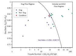
Figure 1. Location of operating point of problem system (shown by star) indicated a small amount of inert gas would stop slug flow.
Figure 1 shows a section of the Griffith-Wallis flow map for a narrow gas-ratio range (~0.75–0.96) based on volumetric flow ratios versus Froude number. (As long as consistent units are used, both axes are dimensionless numbers.) The original correlation was based on a mix of data in small pipes (0.5–1.0 in.). However, data from commercial units (6–8-in. pipes) with hydrocarbons have been added. The data were a very good fit of gas ratio versus Froude number.
In the figure, a star shows the operating point of the problem system; it is very close to the transition line. Because higher-volume gas flows move the operating point up and to the right, injecting a small amount of inert gas into the system eliminated the slugging problem. This injection ended once normal operating rates were re-established.
This map seems a good fit here — but its applicability may not extrapolate to other conditions.
Numerous elements, including pressure drop, void volume, and slug size, play a role in two-phase flow that may be important in specific situations. In this case, understanding of flow regime sufficed to stop the slug flow.
The situation here highlights another important issue: for vertical upward gas/liquid flow, it’s often better to round pipe sizes down rather than up because too large a line size may lead to slug flow. Sometimes, to avoid slug flow, using multiple parallel lines (with valves to remove some from service) may make sense.
About the Author
Andrew Sloley, Plant InSites columnist
Contributing Editor
ANDREW SLOLEY is a Chemical Processing Contributing Editor.


