Process Puzzler: Sort Out a Sewer Snafu
This Month’s Puzzler
Process and Storm Sewers
Figure 1. Backups plague wastewater treatment system.
We’re having problems with our plant wastewater system (Figure 1). First, we can’t seem to get the nominal flow out of our new fiberglass neutralization system — we constantly back up in the neutralizer. Second, the drains in the plant are backing up. Our plant manager is convinced we’re seeing overflow from a 4-in. storm-water line that was in use before the process and storm-water treatment systems were separated back in the 1970s. In addition, the city water plant complains that our wastewater is spilling over into the storm water and corroding the line from two sewer sump pumps. What do you think the problem is and what can we do to address these issues?Check Your Design Basis
I found the velocity, V, using the Darcy-Weisbach equation:
V = (8g×RH×S/f)½
where g is the gravitational constant, RH is the hydraulic radius, S is the pressure drop/run (i.e., head loss per length, h/L), and f is the Darcy friction factor derived from the Colebrook-White equation:
1/f½ = -2log{ε/12RH + 2.51/(Re×f½)}
where ε is the roughness and Re is the Reynolds number.
I solved for fV2 = 8g×RH×h/L and substituted into Colebrook-White:
taking density,ρ as lb/ft3 and viscosity, v, as lb (mass)/ft-sec. (Multiply cP by 6.72×10⁻⁴ for conversion.) I estimated a flow of 9 gpm assuming a 98%-filled pipe.3) unlike Darcy-Weisbach, it only applies to water.)For fiberglass or plastic pipe, the 9 gpm flow rate indicates a restriction. So, take the pipe apart and look for glue-glob joints at fittings. As a rule-of-thumb, never build with a pipe diameter less than 2 in. if the joints are to be glued. And it’s a good idea to be overly generous to avoid problems — this should have been a 4-in. line.Now, let’s look at the PVC pipe. A flow of 122 gpm should be possible for the 6-in. and 8-in. lines at 60% of capacity, i.e., slightly more than a half-filled pipe using a Darcy roughness of 4.9×10⁻⁶ ft for new PVC pipe. For old PVC pipe with a roughness of 6.6×10⁻⁴ ft, 63% of the total pipe area would be required. If there’s blockage in the pipe, then this area simply isn’t available. There is another possibility. Roughness is based on an experiment, not your actual conditions. In addition, there is the flow upstream of the sewer catch basins. Broken concrete isn’t conducive to smooth flow to the basins like well-maintained concrete.Next, consider the city’s complaint about their wastewater line. Given the elevation difference between the plant junction at 663 ft and the storm water junction at 665 ft, on the surface this seems unlikely. However, the top catch basin is at 672 ft, well above the elevation of the storm water junction. If the plant sewer line is plugged and the block valve leaked, it’s possible that the plant water/toxic waste drained to the booster pumps. This line should be inspected and the connection line should be abandoned.Dirk Willard, consultantWooster, Ohio
September’s Puzzler
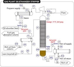
Gas Plant De-Ethanizer Stripper
Figure 2. Brief power failure has caused ongoing problems that prevent restart of the unit.
Our de-ethanizer stripper tripped after we attempted to start up the tower after a power failure that almost exclusively affected the refinery gas unit (Figure 2) — and we’re still trying to restart it. The fluid catalytic cracker and still suffered a ½-sec brownout but everything restarted without trouble. The rest of the refinery may not have been affected. The de-ethanizer trip occurred within a few minutes after we ran into an unexpected compressor trip when restarting the oil absorber upstream of the de-ethanizer. Within seconds after that compressor trip, the topside de-ethanizer high-pressure alarm activated and the top relief valve popped; the pressure control valve at the top of the tower did not open first as expected. What do you think caused our problems? Is it safe to start up the tower again? Have we damaged the compressor? Is there anything wrong with our start-up procedure?Send us your comments, suggestions or solutions for this question by August 14, 2015. We’ll include as many of them as possible in the September 2015 issue and all on ChemicalProcessing.com. Send visuals — a sketch is fine. E-mail us at [email protected] or mail to Process Puzzler, Chemical Processing, 1501 E. Woodfield Rd., Suite 400N, Schaumburg, IL 60173. Fax: (630) 467-1120. Please include your name, title, location and company affiliation in the response.And, of course, if you have a process problem you’d like to pose to our readers, send it along and we’ll be pleased to consider it for publication.


