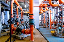
Fluid Handling: Don’t Push Piping Flow Too High
The quest to squeeze out more capacity from a plant may surface even before initial construction is finished. Assessing the maximum additional flow through piping requires special care.
Initial sizing usually is based on balancing constraints including minimum velocity needed, economic pressure drop, and maximum allowable velocity. Because pipes only come in standardized sizes, the chosen pipe often may boast ample extra capacity. Except for special cases, the cost of pressure drop rather than a maximum velocity limit generally sets pipe sizes in new plants. Common exceptions where maximum velocity limits may take precedence include caustic (4 ft/s), concentrated sulfuric acid (4 ft/s), and aqueous alkanolamine solutions (10 ft/s).
Some combination of erosion, corrosion, erosion/corrosion, vibration, static electricity or hydraulic hammer may call for setting velocity limits. These tend to be service specific. So, what general approach makes sense to determine these limits?
Let’s look particularly at erosion in systems. High velocity can damage the piping surface and, ultimately, lead to piping failure, which usually results from some combination of erosion and corrosion. High velocity damages a surface film; the damaged surface film exposes the base piping material and the pipe corrodes. As long as velocity remains high, deterioration continues and can rapidly damage pipe.
Ideally, true single-phase fluid flow should have only minimal erosion rates. Problems tend to occur when two-phase flow hits the surface. Two-phase flow can involve solids entrained by gas or liquid or liquids entrained by gas. In any case, getting past the problem that erosion or erosion/corrosion limits are very system specific still is difficult.
Nevertheless, some guidelines can help. These are not meant to substitute for experience or reduce the requirement to monitor process piping for damage from high velocity flows. Moreover, they demand verification by field observation and data for your specific system.
Recommended Practice 14E (“Recommended Practice for Design and Installation of Offshore Production Platform Piping Systems”) of the American Petroleum Institute (API), Washington, D.C., exemplifies the most common approach to determine a maximum velocity allowed based on erosion or erosion/corrosion. This sets a velocity threshold of:
Ve = c/(ρ½)
where Ve is the velocity in ft/s above which erosion may occur, c is a constant that varies with the system and materials, and ρ is flowing density in lb/ft3 assuming no-slip in mixed-phase flow. Different organizations recommend using c valves ranging from 100 to 160 for continuous flow with carbon steel and up to 200 for corrosion-resistant alloys, with allowable values for intermittent services generally 25% higher.
However, an extensive dispute exists about the reliability of this evaluation. Some argue the equation lacks theoretical justification and simply is an empirical correlation. Yet, little published data support either the form of the equation or the c values often used. So, if you opt for this equation, it is important to understand the assumptions involved.
First, the use was intended for gas/oil/water systems with no solids present. Solids can increase erosion rates dramatically. Second, passing the threshold does not imply a specific erosion rate or defined pipe life. Third, no allowance is made for pipe bends, diameter changes, or other fittings, although changes in pipe geometry clearly are linked to many erosion problems. Fourth, the equation gives a higher “threshold’” velocity for lower mixed-phase density. A lot of experience directly contradicts this. Indeed, much data support the idea that lower bulk densities increase erosion rates in two-phase flow due to local variations in flow patterns.
Some alternative evaluation methods for maximum line velocity exist. However, they all generally suffer from a lack of justifiable data behind them and problems with how to account for flow density.
One alternative is based on the velocity. This is equivalent to making the erosion limit proportional to the momentum of the flowing liquid (rather than its kinetic energy as in API RP 14E):
ρVe/9,272 ≤ k
where k is 4 for 6-in. and larger pipes, 3.5 for 4-in. pipes, and 3.0 for 3-in. pipes.
Another alternative is:
ρVe3 ≤ 45,000
However, the justification for this form is unclear as now the velocity is a cubic function.
Regardless of which approach you use, always remember that, if high velocity is a concern, monitoring of piping thickness is essential and you need system experience to truly understand the actual erosion behavior.
About the Author

Andrew Sloley, Plant InSites columnist
Contributing Editor
ANDREW SLOLEY is a Chemical Processing Contributing Editor.