Don’t Fall Short With Transfer Chutes
Transfer chutes guide and control bulk materials moving from one piece of equipment or place to another, for instance, from one conveyor to the next. These chutes find wide use in many configurations and arrangements.
While chutes are important components in material handling systems, they usually don’t get adequate attention. As a result, they often create bottlenecks in the systems and require extensive maintenance and repair. It is far cheaper to carefully engineer and manufacture a chute than to deal with consequences of a poorly designed or fabricated one. So, here we will discuss practical pointers on engineering, operation reliability and maintenance of chutes.
Design Issues
Ensuring smooth flow of bulk materials without any accumulation or plugging anywhere depends on the proper size and slope of chutes. Different guidelines exist for the cross-section, sizing, slopes and dimensions of chutes. Minimum cross-sectional area of chutes often is specified as 5–8 times the area of cross load of the preceding conveyor (or upstream equipment). Avoid any ratio below 4.5.
Undersized chutes have resulted in blockages and other problems. In practice, chutes should be able to store some volume of material in case of emergency, for instance, malfunction, a temporary stop of the next conveyor or equipment or a surge in upstream conveyor/equipment.
Avoid direct impact of bulk material on the next conveyor belt or piece of equipment. While a very steep angle is not desirable, the slope should suffice to ensure good flow of the bulk material. The optimum angle of inclined surfaces of chutes depend on the specific service and bulk material. However, as a rough guideline applicable to many materials, using a surface inclined at 65° or even 70° of valley angle will properly guide bulk materials. Valley angles below 55° are risky. In addition, the chute design should have a minimum amount of throat constriction and have sufficient support.
Unfortunately, many traditional designs for chutes don’t meet these cross-section and valley angle guidelines, undermining prospects for smooth and trouble-free flow of bulk materials. Indeed, such chutes often provide poor performance.
The bottoms of chutes are frustums of cones or truncated pyramids to aid the discharge of materials. Good chute design requires more than having the correct cross-sectional area and slope.
When bulk material discharges to a chute and impacts the chute surface, its velocity decreases. The larger the impact angle, the bigger the change in velocity. Sliding friction with the chute surface can decrease the material stream velocity even further. If the friction between the bulk solid and the chute walls and wear liners becomes too great, bulk material flow may halt on the chute surface, creating a plugging condition; this not only can cause operational problems but also can present a set of new dangers such as risk of fire or explosion. In addition, flow issues such as “arching,” “ratholing,” etc., can occur. Poor chute performance also can lead to material spillage, considerable dust generation and many other operational problems.
Moreover, when flow abruptly resumes again such as when arches and ratholes collapse, sudden dynamic forces act on the chute or surrounding equipment. These forces can cause structural damage. Also, the development of eccentric flow channels within a chute, particularly due to multiple or offset outlets, can result in non-uniform loading along the outer walls of the chute that may cause wrinkling or buckling of the chute.
The internal surface of a chute must contend with constant abrasion from the flow of material and can suffer wear and damage. Sometimes, such degradation is very fast and can be catastrophic. So, providing replaceable liners made of suitable abrasion-resistant material nearly always is necessary to cope with the impact and erosion. The selection of lining material depends on the service and application. Alloy steel is widely used but ceramic, rubber and other types of linings are available.
Ensuring Adequacy
The engineering, manufacturing and operation of a chute depends on knowing the properties of the bulk material in relation to the flow surfaces. Serious flow problems can result from not having accurate data or not testing the actual bulk material transported and the actual lining considered for the chute. Data from the testing of the specific bulk material and the particular construction materials, such as alloy steel or ceramic liners, are critical. These data will help predict the flow of the material through the chutes and, thus, enable coming up with a design to reduce wear on components and eliminate the escape of fugitive material like spillage and airborne dust.
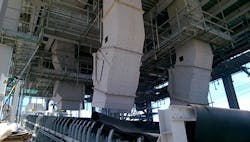
Chutes should be strong and rigid to resist massive forces and potential erosion and corrosion (Figure 1). For commonly used applications, chutes usually are constructed from steel plates of 8-, 10-, 12- or 16-mm thickness or more. Specifically, small and medium chutes (bunkers, hoppers, etc.) generally use 8-, 10- or 12-mm plates. Large chutes (or silos) might need thicker plates, sometimes even 16- or 20-mm ones, depending on load calculations and modelling.
Ease of maintenance is a key consideration. Chutes often are constructed in flanged sections connected with bolting. The number and sizes of bolts are important. As an indication, common chutes use M16 or M20 bolts. Sections requiring removal for maintenance most often are fitted with lifting eyes or lugs located in convenient positions. Frames, flanges, supporting structures or head integral with plate fabricated items should be made from thick plates or properly selected profiles; such flanges typically are fabricated from 16- or 20-mm (or even thicker) plates.
A chute usually comes with a large hinged inspection door — generally at least 600 mm × 600 mm — to enable the clean-out of blockages and to ease inspection and maintenance; necessary maintenance tools may mandate even larger dimensions. The inspection door should be dust tight as well as easily opened and closed without the use of tools.
Gates find wide use in material handling systems to control flow of material in transfer points and different chute systems. They may be placed on the bottom or side of bins, tanks, hoppers or similar equipment to feed materials onto conveyors or other material-handling equipment. However, gates also have other applications — for instance, a flop gate can enable feeding from a single source to two locations. Gates come in many different types and models; they can be manually operated or powered by electric motors or pneumatic actuators. All too often, gates suffer operational problems because of lack of adequate attention to their design, engineering and operation.
Using a proper simulation method to observe and verify the flow of bulk materials in chutes is extremely important. Many simulation and modelling methods, such as discrete element modelling, suit this purpose. These can provide an excellent way to understand material stream flow behavior in a given configuration and enable ensuring optimum material stream trajectory. To reduce wear, you should minimize free fall heights and changes in the direction of material flow. This not only reduces impact forces but also attrition, dusting and fluidization of fine materials. You also can limit dusting by keeping the material in contact with the surface, concentrating the material stream, centering the stream and ensuring it stays in the direction of flow, and maintaining as constant a velocity as possible through the equipment.
It also is necessary for the entire cross-sectional area of the outlet to be active. Any system or equipment used in the outlets should be capable of continuously withdrawing bulk material from the entire outlet. A restricted outlet (e.g., due to a partially open slide gate) will result in funnel flow with a smaller active flow channel regardless of the outlet configuration.
Belt Conveyor Consideration
When feeding a bulk material containing a mixture of fine and lumpy material to a belt conveyor, you can arrange the chute to first deposit the fines on the belt. This bed of fine material then acts as an impact absorbing layer for the more-severe lumpy material.
Off-center or improper loading of the belt is a major problem that poor chutes can create. A chute should place bulk materials in the center of the belt. The direction of the material down the chute should match the direction of the belt travel. The speed of the discharged materials should equal as closely as possible the belt speed. The speed of the bulk material as it leaves the chute depends on the velocity of the material entering the chute, the chute angle, the fall, the material density and the flowability of the material. To increase the speed of material, use a steep chute angle — but angles above 75° result in a rapid decrease in the forward speed. Conversely, reducing the chute angle raises the material speed in the direction of belt travel — but angles less than 55° cause slow flow of the material through the chute.
Each service and application has an optimum chute angle; this optimum angle usually is between 60° and 75°. Heavier materials, because they flow more quickly through the chute, can get by with a relatively smaller chute angle, while light materials require a steeper angle. Lumpy materials tend to tumble and bounce in steep chutes, impeding the material flow. Therefore, while increasing the chute angle is desirable for light materials, for lumpy ones you should limit the chute angle to not more than 70° to prevent this tendency.
In many instances, the material may enter the chute at a very high velocity. A relatively low chute angle would limit, and possibly could retard, the material speed. However, opting for such a chute angle isn’t recommended practice unless the exit speed is close to that of the belt. An alternative means of limiting high lump velocities is to hang baffle bars or similar devices in the path of the lumps.
AMIN ALMASI is a mechanical consultant based in Sydney, Australia. Email him at [email protected].