This Month’s Puzzler
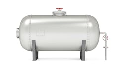
We want to expand our existing storage capacity for biphenyl by adding another, larger tank. We now use a shell-and-tube exchanger to keep the biphenyl in a molten state in the two current tanks. We maintain the temperature between 169°F and 205°F. Properties at the two temperatures are: density, 0.99 g/cm3 and 0.97 g/cm3, respectively; viscosity 1.42 cP and 1.03 cP; heat capacity, 0.382 BTU/lb-°F and 0.397 BTU/lb-°F; and thermal conductivity, 0.077 BTU/hr-ft-°F and 0.076 BTU/hr-ft-°F. The biphenyl’s flash point is 237°F. We use 30-psig steam with a 30°F superheat to heat the biphenyl and don’t allow tank temperature to get within 30°F of the flash point because of past incidents.
The current tanks are 28-ft high and 32-ft in diameter with 4 in. of fiberglass insulation on their sides. The new tank is 32-ft high and 42-ft in diameter with 6 in. of insulation, including on the top. Typically, we run the tanks at about 75% level after a production run. The winter design temperature is 0°F with a 10-mph wind.
We lack data on the heat exchanger but determined its flow rate is about 140 gal/min instead of 180 gal/min in the spec., and the heat transfer coefficient U is only about 56 BTU/hr-ft2.
I’m concerned about whether the exchanger can cope with a third tank. In the winter, the heater already runs about 17 hr/d to heat the two existing tanks. Moreover, the piping is over 300-ft back and forth to the new tank — and it’s overhead.
Corporate managers want to rely on the current heat exchanger and put in a new pump and piping (at $22,000 for the new pump and $348/linear ft for piping). I instead suggested installing a dedicated heat exchanger for the tank and using a pump we can borrow from another plant. The new heat exchanger would cost $23,000 and require only about 150 feet of new pipe. How do I sell my idea to corporate? Am I missing some reason why they want to only use the existing heat exchanger? Can you suggest any way to improve the system?
[callToAction ]
Check Your Design Premise
One bit of information that’s missing is the cost of the old heat exchanger; depending how long it’s been installed, it may have depreciation value in the economic analysis. Also missing are more details on the new heat exchanger. It’s difficult to compare the two options fairly without evaluating reliability. A cheap shell-and-tube heat exchanger without an expansion head may work well for a few years — but then suffer catastrophic failure, erasing any savings in capital expenditure. Making such a comparison often is a challenge because quality improvements and reliability improvements are based on estimates. Maybe corporate knows something you don’t know and doesn’t want to buy a very expensive heat exchanger like, say, a spiral one.
Developing design data, such as U, from trend data can be risky. Presuming fouling is a problem — which it probably is — if the estimated U is only 56 BTU/hr-ft2, then what makes you think the fouling won’t affect your hydraulic calculations for sizing the pump? Most sizing software relies on the Darcy-Weisbach equation, which assumes Newtonian fluid. Maybe you need another type of pump than the tried-and-true centrifugal. Another issue is the borrowed part. Used equipment, regardless of whether it comes from an external or internal source, can pose issues based on past abuse; consider conducting a hydraulic test at a manufacturer’s shop before accepting it as good as new.
Let’s consider constructability of the project. This could be how you sell your idea to corporate. Using the existing exchangers involves at least two tie-points, likely four, and perhaps more if there are cleaning connections. Always figure tie-points at time-and-a-half, perhaps double-time — and that’s assuming the existing isolation block valve doesn’t leak. Construction in racks can be expensive, requiring erection and disassembly of scaffolding. Power supply to the welder in the racks will rack somebody’s brain. Then there’s lighting. Issues like those help explain why 60% of capital projects miss their budget targets. If you build fresh, all you must worry about is the area around the new tank; you can work on straight time and probably avoid high scaffold work by making tie-points near the ground.
As for loading up the duty on the existing heat exchangers, I really don’t see a problem. If you can switch back and forth between exchangers, then you possibly can use the two heaters to maintain three tanks. If you have problems, raise the setpoint of the heaters and look into added insulation. You may want to optimize on the level by heating and raising the level in the tank; this will provide more mass that should retain heat better between heat-ups. I’m not sure what you can do about the controls. Some kind of batch control with priority based on which tank is closest to the melting point might work.
Dirk Willard, consultant
Wooster, Ohio
Delve Deeper
It seems there are two problems: 1) heat exchange and 2) fluid flow.
The problem has been well presented and it seems the engineer involved has a good understanding of what is needed. However, that needs to be justified in financial terms so the money people understand. If they are willing to spend [$22,000 + ($348 x 300) =] $126,000 that tells us that the company has the budget, if I understand the problem as described. It is up to the engineer to calculate beyond a shadow of doubt using all the information at hand to show the value of her or his suggestion. Spending [$23,000 + (348 x 150) =] $75,200 makes sense but it seems there is a miss.
Using the desired flow rate, the engineer must do heat transfer calculations. This may require some guesstimates based on the flow rates and process conditions. What-if analysis using different flow rates and production needs is necessary. Every permutation/combination must be looked at.
I am not clear why the flow rate has dropped. Are the tubes of the heat exchanger plugged? They should not be. Has the steam flow rate dropped?
Bottomline, the engineer must do additional homework to make a case for the new heat exchanger and associated piping. That person is thinking sensibly and is on the right track but has to financially justify how the operation can be simplified and warranted.
Girish Malhotra, PE, president
EPCOT International, Pepper Pike, Ohio
June’s Puzzler
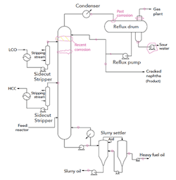
Our plant decided to make some repairs to the top trays in the main fractionating tower above the light cycle oil (LCO) stripper in our fluid catalytic cracker. We suspected trays were leaking based on the temperature profile and high level in the LCO stripper below the trays. We scheduled repairs during an outage. During that shutdown, we found corrosion of stainless-steel/carbon-steel welds affecting four trays. When we got inside, I noticed several weld repairs that didn’t appear in the maintenance files. I then talked to people about past weld repair work on the system and recorded what I could find (see Figure 1).
Figure 1. This tower in a fluid catalytic cracker unit suffered from corrosion.
A severe thunderstorm caused the power to fail for half a day during the hydrostatic test, delaying the startup. So, staff rushed commissioning to meet the turnaround window. Although tower performance has improved, it’s still not quite where it should be. The liquid level in the LCO stripper seems high and the pump-away motor amps seem low. The temperature elements in the middle-bottom of the column don’t seem right because the difference between the trays is small. The pressure transmitter above the reboiler isn’t working correctly.
In fact, when reviewing the commissioning records, I noticed that many transmitters weren’t checked in an effort to cut startup time. I’d like to run a simulation but don’t have any reliable data above the feed tray for comparison.
The unit superintendent blames the corrosion on the wash procedure that maintenance uses. Maintenance says corrosion from periodic washing is impossible. Our process group says the concentration of caustic used for washing is high and the wash temperatures are too hot. (We use 10-psig steam reduced from a 450-psig system.) However, they agree with maintenance that the washing isn’t the culprit.
This is as far as I’ve gotten in my investigation. Have I missed anything? What else should I look for? Is there room for improvement in the wash procedure? Should I worry about corrosion reported at the bottom of the tower? (Maintenance says this is normal.)
Send us your comments, suggestions or solutions for this question by May 10, 2019. We’ll include as many of them as possible in the June 2019 issue and all on ChemicalProcessing.com. Send visuals — a sketch is fine. E-mail us at [email protected] or mail to Process Puzzler, Chemical Processing, 1501 E. Woodfield Rd., Suite 400N, Schaumburg, IL 60173. Fax: (630) 467-1120. Please include your name, title, location and company affiliation in the response.
And, of course, if you have a process problem you’d like to pose to our readers, send it along and we’ll be pleased to consider it for publication.


