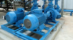
The centrifugal pump is a workhorse in the process industries. However, the way such pumps are used frequently undermines their efficiency. In particular, system designers typically oversize pumps during the design stage to ensure the pumps provide the needed flow. In addition, the methods used for flow control often are wasteful. In this column, we address this pervasive pair of problems.
Throttling valves. A valve on the discharge side of the pump controls the flow. This is the most common form of centrifugal pump control. Partially closing the control valve (or balancing valve in a static application) at the pump discharge is a convenient but inefficient way to reduce the flow of an oversized pump. As the control valve closes, it reduces the flow rate — but adds frictional resistance the pump must overcome.
Flow resistance due to throttling wastes a considerable amount of energy if the valve constantly stays heavily throttled (say, <60% open). The most common improvements are:
- Trim the pump impeller. This is a low-cost option and typically a good solution if the required flow always is less than design, the flow reduction isn’t too large, and the required flow rate is fairly constant. (However, predicting resulting performance demands care; see: “Centrifugal Pumps: Avoid Surprises When Cutting Impellers.”)
- Install a variable frequency drive (VFD). VFDs save energy as the pump’s speed is reduced. They are an ideal solution if the pump’s capacity varies widely. However, VFDs are comparatively expensive and can’t always be justified. (For tips on applying VFDs effectively, see: “Consider VFDs for Centrifugal Pumps.”)
- Install a right-sized, high-efficiency pump. If the pump is significantly oversized for its maximum flow requirement or if its hydraulic efficiency at the normal operating point is low, this may be the best option.
Recirculation. With recirculation, the pump produces a constant flow greater than the maximum process demand. Fluid required by the process goes to downstream equipment while the excess fluid flows, via a recirculation line with a control valve, directly back to the suction tank. The constant recirculation of excess fluid makes this the least efficient form of flow control.
However, recirculation can serve an important function by providing minimum flow protection. If the flow through a pump falls too low, pump damage can result from rapid heating of the fluid within the pump as well as induced pressure pulses originating within pump suction and discharge areas by recirculation vortices. Stopping the recirculation flow when it’s not needed to protect the pump can achieve more-efficient minimum flow protection.
In addition, you can arrange automatic control valves for recirculation to open only when the system flow is below the pump’s minimum flow requirement. A pressure sensor in the pump discharge line can control the valves and open them at a high pressure, or you can use a spring-controlled mechanism set to open automatically at a pre-defined pressure. This arrangement greatly improves the control system’s energy efficiency.
Parallel pumping with throttling valves. Here, multiple pumps piped in parallel discharge into a common header. This arrangement usually relies on throttling control valves to regulate flow in different lines coming off of the main supply header.
An opportunity to save energy often exists in constant-speed parallel pumping systems having more than three pumps. This is because the last pump started generally doesn’t add a large amount of additional flow to the system. The fourth or fifth pump typically runs as an “insurance policy,” in case one of the other pumps fails. However, this insurance policy can be expensive. Turning one pump off and installing automatic controls capable of starting an additional pump if the header pressure falls below a pre-determined level can ensure proper operation with fewer pumps and lower energy costs.
For further details and examples, see: Glenn T. Cunningham, “Rotating Equipment: Centrifugal Pumps and Fans,” Chapter 15 in “Energy Management and Efficiency for the Process Industries,” Alan P. Rossiter & Beth P. Jones, Wiley-AIChE, 2015, pp. 186-206.


