THIS MONTH’S PUZZLER
We manufacture product in a 4,000-gal reactor operated at 150 psig that has a conventional steam-heated jacket. We’re considering a project to cool a batch after a reaction using an external plate heat exchanger: the project involves doubling the size of the product pump and adding a plate-and-frame exchanger. Presently, a shell-and-tube exchanger handles cooling: product flows through the shell side of a 1,2 exchanger (2 shell passes); 85–115°F cooling tower water provides cooling. The area is about 2,500 ft2. Currently, the contents of the reactor take four hours to heat up with 35-psig steam, and fifteen hours to cool down with cooling tower water, before being pumped to storage as product. The reactor’s jacket provides heat for initiating the reaction and heating the ingredients in the early steps of the batch. A waxy material added in the beginning would form a second phase and precipitate without heating; this problem disappears when the material reacts with the aqueous phase. A multi-speed agitator, running at 120 rpm early in the batch, often is turned off altogether because of foaming in the middle of the process cycle. The only circulation then is by a 100-gal/min pump circulating fluid through the product heat exchanger with water off. We want to cool the product from 250°F to 125°F, near the product gel point. Can you suggest a better way to speed up cycle time and reduce heating and cooling time?
INJECT THE WAX AT THE PUMP
The problem is not very clearly defined. Thus I am making assumptions. Before I invest money I would consider the following option. If you can achieve your result, you might not need to invest. The results of this experiment could give you better operating options and could lower your investment.
I am assuming that the waxy material is a reactant. I would consider pumping this material as a melt at or before the inlet of the recirculating pump. The reaction exotherm should raise the batch temperature and would also speed the reaction, i.e., reduce the batch cycle time. I would also use the heat exchanger to raise/control the batch temperature so that the reaction time is reduced, i.e., batch cycle time is lowered. I would initially use the reactor jacket to heat the batch and use it later to maintain the batch temperature. Addition of waxy material at the pump might eliminate the foam formation.
I would also review why the batch temperature has to be raised to or maintained at 250°F. Is it because the reaction is not complete or some other reason? If the batch can be maintained at a lower temperature, I would consider that option. I hope review and consideration of the suggested option would give you significant clues. I believe that you have sufficient heat exchange capacity to double your production.
Girish Malhotra, president
EPCOT International, Pepper Pike, Ohio
FIX THE JACKET
Increase the surface area for cooling by piping up cooling water to the reactor jacket. When you need to go from heating to cooling mode on the reactor, you will want to drain the condensate out of the jacket. So, install a drain valve and vent valve on the jacket. After the condensate is drained, shut the drain and vent valves and open the new cooling water supply and return valves to the reactor jacket. The additional surface area you get by using cooling water in the jacket is about 300 ft2, which should decrease your cooling time by 1½ hours. After you finish cooling the reactor, you will want to drain the jacket so as not to contaminate the condensate return with cooling water. This doesn’t significantly decrease your cooling time, but it helps.
Michael Dobrowolsky, controls engineer
SI Group, Rotterdam Junction, N.Y.
LOOK AT THE PROCESS STEPS
Somewhere in the development of this product, the design went wrong. When I was at Andrew Jergens, we ran into a similar problem. As the process engineer during a product development I witnessed the process in the laboratory. I asked for a change in the procedure to move the addition of the foaming ingredients to as late as possible in the batch. And I designed the reactor jacket for dual use, i.e., heating and cooling.
Your biggest problem will be showing management that heating and cooling with an external heat exchanger is expensive and inefficient. Putting in a massive pump and improving heat transfer by a more-efficient heat exchanger won’t reduce batch times, at least not as much as will modest changes to the process — mostly involving process control. And these changes can be done more easily by adding controls with little loss of production time; replacing an exchanger and installing a pump may cost perhaps three to five days.
Tie into a chilled water or cooling water line; install an automatic valve and connect it to the current steam control valve. Add an automatic valve to the steam line upstream of the control valve. Of course, you’ll want to confirm that the current control valve functions well in cooling and heating. If not, install a suitable larger cooling control valve bypassing around the steam control valve when cooling. In this event, you should expect some cross-contamination between the two lines.
Let’s consider the heating and cooling times in detail. Use the following equations from D.C. Kern’s “Process Heat Transfer,” McGraw-Hill, 1951: equations 18.9, 18.11, 18.16, and 18.17. “Nomographs for Unsteady State Heat Transfer” by Stephen Zakanycz and Jerome Salamone, published in the January 1963 edition of Industrial and Engineering Chemistry, provides a useful application of Kern’s equations. Assume the following generic specific and derived physical properties for these equations: C (cooling water) = 0.98 Btu/lb-°F; c (product) = 0.7 Btu/lb-°F; U = 150 Btu/hr-ft2-°F for the jacket; and 28,350 lb for M, mass of the batch with a specific gravity of 0.85. See this site for this application.
The jacket area is 220 ft2 for an ASME-standard dished tank 72 in. in diameter with a 15-ft straight side and a working volume of 4,200 gallons at 90% full. I would assume 600 for the plate-and-frame heat exchanger U, an area of 1,000 ft2 and a product pump rate of 100 gpm to the exchanger with a cooling water rate of 400 gpm, to make the contest sporting. I would assume 30 gpm through the jacket. Now, let’s consider how to reduce batch time.
The heat-up with steam is difficult because only a portion of the jacket is exposed. Heating bare wall as the tank is filling is ineffectual. In this situation, the plate heat exchanger could be useful; always consider the limits of plate gaskets: http://goo.gl/4nSvo3. A welded plate may be suitable; 300°F is the limit for most frame gaskets. Typically, a plate-and-frame exchanger offers a 3–4 times improvement in U compared to a shell and tube; a modest improvement in minimum temperature approach also may be possible: 5°F compared to 10°F. With only the jacket or a coil, the solution involves an iteration; ideally, set up an Excel file to do all calculations in a single row, then repeat using delta time and level as parameters.
Cooling is a clear winner for the jacket as I will demonstrate. For a jacket or coil, Kern (Eq. 18.11) developed the following approximation for cooling time:
q = ln[(T1 - t1)/(T2 – t1)]/[(wc)/(MC)×{(e(UA/(wc) -1)/e(UA/wc)}], where T1, T2 are the initial and final temperatures of liquid in the reactor, t1 is the initial temperature of the cooling liquid in the coil or jacket, w is the mass rate for the cooling medium in the jacket or coil in lb per hour, M is the mass of reactor liquid in lb, c and C are the heat capacities of cooling liquid and reactor liquid, respectively, A and U are for the jacket or coil, and q is in hours. For an external heat exchanger, Kerns equation 18.17 applies:
q = ln[(T1 - t1)/(T2 – t1)]/[ (K4 -1)/M×{W(wc)/(K4(wc) – WC)}]
K4 = eUA[1/WC – 1/wc]; w and t1 now refer to the cooling medium going through the exchanger.
Comparing the two cooling methods — using the terms assumed above — shows a cooling time of 4.5 hours for the jacket and 11.5 hours for the exchanger. Of course, you could increase the exchanger’s area and the product flow to it. For example, using the Kern equations, I come up with 17 minutes for cooling using an area of 1,200 ft2. You also could argue that the jacket flow rate is high: I get about 9 hours cooling time at 15 gpm. This analysis has several problems: fouling could increase as the product is cooled; and U changes slightly as the product temperature drops.
The real question is whether management should expend money for a new exchanger and whether sufficient cooling water is available. These decisions only can be addressed based on product demand. This is out of the realm of engineering.
Dirk Willard, senior process engineer
Ambitech Engineering, Joliet, Ill
CONSIDER SEVERAL FACTORS
We propose a few things that may be considered regarding cycle time:
1. When in the process do you heat up the batch? If it’s at the beginning, then heating will have to be maximum at 125oF to add any extra material such as the waxy material you use in the batch.
2. Have you ever used antifoam that is specifically made to apply in food products? If not, then the solution is to use antifoam. Do not exceed 300oF. Above this temperature antifoam becomes toxic.
3. The cooling process is not efficient. Do you use a water reservoir to circulate and recycle the tank to cool off? If yes, then this process is not the right one. Because, if the same water that touches a very hot tank comes back to the reservoir, it will increase the temperature of the rest of the water ,extending the time to achieve 125oF degrees. Instead, we suggest running cold water thought the tank jacket from bottom to top without recycling the water to the reservoir. We estimate this process will only take a maximum of 4 to 5 hours to cool off.
Miguel Ortiz, Fabricio Barrera, Washington Miranda, supervisors,
Pharmachem Laboratories, Kearny, N.J.
SEPTEMBER’S PUZZLER
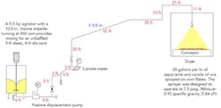
We are suffering an excessively high level of rejects from our process to coat corn flakes with aspartame (Figure 1). Instead of individual flakes, we see clumps coming out of our dryer. Only about a third of our product gets packaged — the weigh cells on the dryer exit conveyor reject the rest of the flakes as over-weight because of clumping. I’m convinced we have a mixing problem. An instrument engineer says the Coriolis meter is plugged. The plant engineer is certain the spray nozzle is fouled. And a production foreman says we’re not properly sifting the aspartame added to the mixer. Aspartame is expensive, more than $800/lb. What do you think is causing our problem and how do we fix it?
Figure 1. Excessive clumping afflicts corn flakes coming out of the dryer.
Send us your comments, suggestions or solutions for this question by August 15, 2014. We’ll include as many of them as possible in the September 2014 issue and all on ChemicalProcessing.com. Send visuals — a sketch is fine. E-mail us at [email protected] or mail to Process Puzzler, Chemical Processing, 1501 E. Woodfield Rd., Suite 400N, Schaumburg, IL 60173. Fax: (630) 467-1120. Please include your name, title, location and company affiliation in the response.And, of course, if you have a process problem you'd like to pose to our readers, send it along and we'll be pleased to consider it for publication.


