The emergence of radar has significantly advanced level monitoring. Radar provides cost-effective and accurate measurements that are immune to density and other process fluid changes, as well as most vapor-space conditions.
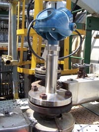
Radar level measurement systems come in contacting and non-contacting versions, both of which are widely applied in the process industries. Contacting generally is a good fit for small spaces; it easily replaces older technologies such as displacers and capacitance probes. Non-contacting usually is better for dirty, viscous or corrosive applications and when agitators are present. Currently, contacting devices called guided-wave radar (GWR) are slightly more prevalent, primarily because they can measure interface level (e.g., oil and water) as well as standard direct level (Figure 1).
There are some important considerations when applying both types of radar technology. For example, getting accurate measurements in steam applications of more than 400–500 psi (30–35 bar) requires GWR systems that have dynamic vapor compensation. Similarly, in applications where signal reflection is weak, you must select a device with technology that minimizes losses in the returned signal. In cases -- including some solids applications and those with low dielectric fluids and turbulence due to boiling or entrained air -- where the return signal is so weak that it occasionally disappears, the device should be able to provide a level measurement via alternative methods such as probe end projection (which uses a combination of the known length of the probe and an online reading of dielectric to calculate level).
While GWR works in many conditions and doesn't depend on reflecting a signal off a flat surface, probe choice requires care. Probes come in several styles -- the application, length and mounting restrictions influence the correct choice. Unless coax-style units are used, probes should not directly contact a metallic object because that will impact the signal. Twin and coaxial probes are susceptible to clogging and build up. If the application involves liquids that tend to be dirty, sticky or can coat, then only use single-lead probes. For such applications, devices offering signal quality diagnostics can help determine if the probe needs cleaning and allow scheduling of maintenance only when needed.
In general, GWR doesn't suit extremely viscous products where fluid flow is minimal. If GWR is used with very viscous fluids and installed in a bypass chamber, heat-trace and insulate the chamber to ensure fluidity. In addition, check that the connections from the tank to the chamber and the chamber's diameter are large enough to allow good fluid flow. For applications such as asphalt where heavy coating is likely, go with non-contacting radar and mount directly on the vessel, not in a chamber.
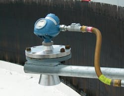
Non-contacting radar (Figure 2) demands careful consideration of process conditions and installation constraints. It requires a clear unobstructed view of a liquid surface. An unrestricted mounting nozzle also is important. The measured surface must be relatively flat, not slanted. Non-contacting radar gauges can handle agitation -- but success depends on the fluid properties and the amount of turbulence not limiting the return signal too much. Low dielectric fluids reflect very little radiated energy back to the gauge. Additional signal loss occurs if the liquid surface is turbulent, whether from agitation, product blending or splashing. To overcome this, you can use bypass pipes -- including self-contained chambers or stilling wells to isolate the surface from turbulence.
Such bypass pipes (Figure 3) provide a calmer surface in case of turbulence. They offer external mounting with valves, allow for easier servicing of level devices and enable radar measurement in tanks such as towers that only offer side connections. Always provide multiple holes or slots on one side of the pipe to ensure good fluid flow-through.
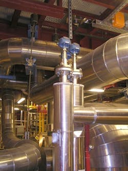
Both GWR and non-contacting radar work well for pipe or stilling well applications, but GWR is far simpler to install and maintains accuracy and sensitivity independently of the pipe. For these types of applications, correctly dimensioning the chamber and selecting the appropriate probe are essential.
Choose 75-mm or 100-mm chambers. Smaller ones raise risks of build-up and flow-through problems, and increase the chances of the probe contacting the chamber wall.
Select a single probe, as it is less susceptible to build-up. Most chamber installations rely on rigid probes but flexible ones also may also be used. Ensure the probe is suspended vertically and does not touch the pipe wall. A "centring" disk can keep the probe properly positioned away from the wall.
For shorter pipes, use GWR with rigid probes. GWR with flexible probes can work in long pipes, but the probes must remain taut and away from the wall. A combination of weights and centring disks can achieve this. For longer pipes or when head space for installing probes is limited, opt for non-contacting radar.
SPECIAL CHALLENGES
Several types of applications raise particular issues.
High temperature and pressure. Applications with extreme temperature and pressure conditions demand a heavy-duty process seal with multiple layers of protection and a flexible assembly to handle the stresses and the forces induced. This is to prevent leakages and ensure the safety and efficiency of your plant.
When measuring liquids at very high temperatures in a chamber, you must insulate and heat-trace the chamber. Fluctuations in temperatures alter the density and volume of the liquid, which then affect the level in the chamber. Maintaining the temperature of dirty liquids such as heavy oil also helps avoid clogging and sticking within the chamber and enables adequate flow-through.
Although radar technology is not affected by density changes, dielectric variations can have an impact. For boiler and feed-water systems where boiling water and high-pressure saturated steam vapors are present, the returned signal from the surface becomes weaker as water temperature increases. In addition, the saturated steam alters the propagation velocity of the radar signal and generates an error in the level reading proportional to the measured distance. Dynamic vapor compensation can address the changes in the vapor-space dielectric and reduce the incorrect distance caused by varying pressure or temperature to less than 2%.
Interfaces. The fluid with the lower dielectric must always be on top and you must know its dielectric value. The two liquids must differ in dielectric value by at least around ten. Effective measurement requires certain thicknesses of layers. Typical successful applications have a hydrocarbon-based fluid with a dielectric around two as the top layer and water-based fluid with a dielectric over 40 at the bottom.
Applications where the densities of the two fluids are very close or where emulsifiers are used can produce fairly large emulsion between the liquids. This may make the interface indistinct. Heavy and thick emulsion layers or liquid layers with similar dielectrics can pose a problem for GWR because it requires a distinct dielectric difference to detect the interface. GWR devices have proven to work in interfaces with emulsions but success is difficult to predict. The interface threshold on the radar device may require manual adjustment.
In applications with large emulsions, a displacer device (which relies on a buoyancy effect rather than any dielectric value) can track the midpoint of an emulsion layer and, so, may provide a better solution. However, that technology relies on moving parts that require frequent cleaning and replacement, thereby reducing the reliability of the measurement and incurring greater maintenance costs.
Open air and non-metal tanks. Radar often works well in such applications. In some cases, though, outside disturbances may interfere with the radar signal -- and you must select a device, such as a GWR with a smart galvanic interface, with high resistance to electromagnetic interference. For most open sump and well installations, an ultrasonic meter is a more-cost-effective solution. However, should vapors be present, choose a low-frequency radar device instead.
Overfill protection. In critical applications, you must install a minimum of two level technologies or devices; if several measurements rely on the same technology, you must employ a voting scheme. Using technologies less influenced by process conditions, such as radar in combination with vibrating fork switches, is a good step to more accurate and reliable measurements.
For radar, most failure modes relate to a loss of signal. High sensitivity normally results in high availabilities. High sensitivity is achieved by increasing the signal-to-noise ratio, e.g., via Dual Port and Direct Switch Technology. Enhanced echologics -- the ability to ignore false echoes -- and smart software functions also improve radar performance. Some GWR devices incorporate software that improves measurements in the near zone (high level areas), especially for low reflective targets.
However, above a certain level the surface echo may not appear at all in the waveform. Using echologics to monitor signal changes as the level gets close to the top adds an extra layer of protection. This supports the basic level signal and gives informative warnings that the tank is full, even if the level signal is lost.
Advanced diagnostics is another step in the right direction for safe measurement. For example, some GWR devices provide real-time notification if the probe gets coated, providing the opportunity to schedule proactive maintenance.
Today, vibrating fork switches continuously monitor corrosion of the forks, external damage to the sensor, internal wire disconnect or breakage, and over-temperature. This results in a fault indication and fail-safe operation of the switch output.
INSTALLATION PITFALLS
A good installation is key to success with radar. A new radar device usually is installed on an existing nozzle. This nozzle sometimes may be too tall or narrow for the instrument. Try to minimize the height of the nozzle used. Ideally, nozzles should be at least two inches in diameter but no more than six inches high for GWR. For non-contacting radar, the end of the antenna should extend slightly beyond the nozzle. High-frequency non-contact radar can use longer nozzles but they must be smooth and clear of obstructions.
Positioning the nozzle directly over a pipe, baffle or other obstruction can cause problems. The obstruction interferes with the radar beam and it, rather than the process medium in the vessel, becomes the level measurement. Similarly, a fluid stream coming into the tank that falls into the path of the radar beam or on the probe will impact the reliability of the measurement.
As with all instrumentation, you must correctly configure radar devices in accordance with application needs. Take special care when inputting thresholds for the radar signal -- these will change depending on the medium being measured. For example, oil appears very different to a radar device than water and, therefore, requires very different threshold settings. However, today good set-up guides and functions in most cases enable easy configuration in just a few steps.
SARAH PARKER is level application manager for Emerson Process Management, Chanhassen, Minn. Email her at [email protected].
