Plant Insites: Getting the Most from Your Heat Exchanger’s Baffle Design

When it comes to shell-and-tube exchangers, the way a baffle is cut can quietly make or break performance when an exchanger is moved into a new service.
Shell-and-tube heat exchangers use baffles on the shell side to direct the shell fluid across the tube and prevent direct flow from the inlet nozzle to the outlet nozzle. The most common baffle is the single-segmental baffle with part of the baffle plate cut away to allow flow across the bundle.
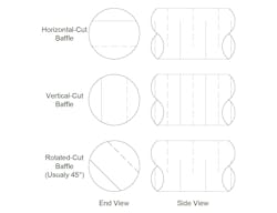
Figure 1 shows three standard baffle orientations: horizontal cut, vertical cut and rotated cut. Typically, a rotated-cut baffle is at 45° but can be mechanically built any way the user wants. However, typically there is no benefit to any other rotated cut except 45°. All the examples in Figure 1 show a baffle cut of 25% (one-quarter of the diameter cut away), but baffles can have varying cuts.
Understanding the Default Baffle Orientations
Exchanger vendors often handle details of the baffle-cut orientation for a new shell using some standard service guidelines. However, over the years, exchangers get moved into new services and different environments. Looking at how different baffle orientations affect exchanger performance can provide a better idea of how the baffle-cut orientation can affect operation.
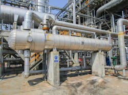
Most exchangers have the inlet and outlet on the shell side on the top and bottom of the shell as shown in Figure 2.
This configuration allows for straightforward exchanger venting during startup. The discussion here focuses on this common setup with the inlet and outlet shell-side nozzles on the top and the bottom of the exchanger. However, some exchangers have inlet and outlet nozzles on the shell side at 45°, and even other positions, from the vertical centerline.
The horizontal-cut baffle configuration is the most common. This allows for good operation with single-phase flow on the tube side. Unless there is some special reason, this is the default configuration suitable for most services.
Vertical-cut baffles are the default used in phase-change services, including both condensing and vaporizing. In most of these services, the outlet is two-phase and should normally be on the bottom of the shell to allow for proper draining. This configuration works best if the phase change is close to isothermal.
Vertical baffle exchangers may allow for phase separation on the shell side. If the mixture has a large glide, which is the temperature difference between dew point and bubble point, the phase separation can leave a light vapor mixture in the top of the exchanger and a heavy liquid mixture in the bottom.
A large glide can limit exchanger performance by causing heavy liquid in the bottom that’s difficult to vaporize or light vapor in the top that’s difficult to condense. One solution includes variable baffle spacing to maintain mixture velocity. Switching to a horizontal exchanger is another possible solution to issues with glide, though it will have a higher pressure drop due to liquid pooling, which is typically more severe in condensers with low liquid volumes.
Evaluating Performance When Exchangers Move to New Services
This brings us to the third option, the rotated-cut baffle. The only significant benefit of a rotated-cut baffle is the creation of a single-phase flow across the bundle, similar to that of a rotated-square pitch exchanger using a conventional square-pitch layout. The flow pattern on the rotated-square pitch gives better heat transfer for highly viscous liquids.
The way the baffles are cut and whether the unit was designed for single-phase or phase-change service can make a surprising difference in how it performs.
Take a horizontal-cut exchanger. You can move it into a phase-change service, but expect some compromises, including higher pressure drops and potential drainage issues.
A vertical-cut baffle, on the other hand, doesn’t always play nicely in a single-phase role. Parts of the surface can go effectively “dead.” How serious that problem becomes depends on the details—nozzle placement, baffle layout and other design nuances.
Then there’s the rotated-cut baffle, something of a middle ground. Put it into a conventional single-phase service and you might still see a bit of dead area but usually much less than with the vertical-cut type. Move it into a multi-phase service, though, and it tends to perform almost as well as a vertical-cut baffle.
The conventional approach of using horizontal baffles fits most cases. Keeping track of the internal baffle orientation, nozzle orientation and internal flow patterns gives you a better understanding of when to use vertical and rotated baffle cuts. Additionally, when reusing exchangers, an understanding of internal flow inside the exchanger helps explain performance changes.
About the Author

Andrew Sloley, Plant InSites columnist
Contributing Editor
ANDREW SLOLEY is a Chemical Processing Contributing Editor.