Prevent Backflow into Vacuum Towers During Upsets
Oct. 4, 2024
4 min read
How do you seal a vacuum system that uses vacuum jet ejectors? To find the answer, we’ll pick up from a previous column, “Is a Check Valve Really the Right Answer?”
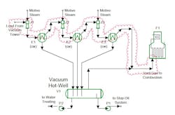
Figure 1 shows a sample system. Three stages of ejectors (J1, J2, J3) take load from a vacuum tower, compress it up and discharge it slightly above atmospheric pressure. In this case, the vent gas from the last condenser (E3) and the vacuum hot-well (V1) include significant quantities of hydrogen sulfide. In fact, in some refinery services, the hydrogen sulfide content of the vent gas may exceed 50%. To dispose of the gas, the traditional approach was to send it to a nearby fire heater. The gas would be burned in a modified burner in the heater, converting the hydrogen sulfide to sulfur oxides.

Key Takeaways
- Hot-Well Modification for Safety: Sealing the vent leg inside the vacuum hot-well improves system isolation during upsets, preventing backflow of hot gases.
- System Sealing Mechanism: Liquid rises in the vent line, maintaining a seal when ejectors fail, ensuring safety as long as pressure and liquid levels are properly managed.
- Reliability of Seal-Leg Systems: The modified seal-leg system is highly reliable and low-maintenance, making it a preferred method for isolating vacuum columns.
The benefit of this was that the heater firebox was normally operating at close just below atmospheric pressure, allowing for disposal without having to compress the off-gas. Burning the vent gas is less common today because of environmental restrictions on sulfur oxide emissions. Nevertheless, many jurisdictions still permit it.
In one such case a concern was raised about what might happen upon loss of motive steam during a major upset. Under those conditions, the vacuum ejectors would no longer pull vacuum. The downstream heater firebox is at a higher pressure than the upstream vacuum tower. Without the ejectors working, hot firebox gas could follow the route shown in the cloud in Figure 2 and enter the vacuum tower. The safety concern was that the hot firebox vapors, still containing some oxygen, would combust with hydrocarbons in the vacuum tower. My previous column discussed some elements of this.
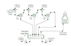
Here, we will focus on how to modify the vacuum system to isolate the vacuum column even if the vacuum system no longer works. The solution modifies starts with looking at the hot-well (V1). Figure 3 shows a different hot-well configuration with the non-condensable vapor from the final ejector cooler (E3) entering the hot-well instead of going directly to the fired heater. In this configuration, the vent line seals inside the hot-well by dropping into the liquid layer. The sealed vent leg does have some disadvantages [1]. However, it does have two advantages. The first is that back pressure on the seal leg makes taking a sample of the vent gas easier by slightly pressurizing the vent gas.
If the ejectors stop working, the pressure in E3 drops because of back-flow into the upstream vacuum tower. Liquid rises up the vent line until the static head of liquid in the line balances the difference in pressure between E1 and V1. The system stays sealed as long as three criteria are met. First, pressure in V1 is low enough – in the case shown, the pressure will be very close to atmospheric pressure because the fired heater is close to atmospheric pressure. Second, the height between E3 and V1 liquid is more than the necessary static head. For a well-designed vacuum system, that should be true because the same height is required for the seal legs from the vacuum condensers (E1, E2 and E3) to the drum. Third, enough volume of liquid is available in V1. This can be done by carefully setting the liquid levels in the hot-well and making the hot-well large enough. A series of baffles in the drum isolates the needed seal liquid from the level controllers on the drum.
One other small modification needs to be made. The final ejector (J3) needs to have a higher maximum working discharge pressure margin. The ejectors now have to discharge to the hot-well pressure plus the back-pressure from the seal leg instead of just the hot-well pressure. Potentially this can cause the final ejector selected to have a slightly higher steam consumption, but this is usually a very low fraction of the entire ejector system steam demand.
The seal-leg system for preventing back-flow is essentially 100% reliable and low-maintenance. It may require a slightly larger hot-well and does have some operating disadvantages – but if isolation is desired, it is clearly the preferred approach.
[1] SLOLEY, A. W., 2005. Bygone designs create current problems. Chemical Processing. November 2005. Vol. 68, no. 11, p. 53–54.
About the Author

Andrew Sloley, Plant InSites columnist
Contributing Editor
ANDREW SLOLEY is a Chemical Processing Contributing Editor.
Sign up for our eNewsletters
Get the latest news and updates