Mind Equipment Modifications
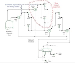
A client modified a vacuum tower to increase capacity and a cascade of other changes followed. One of these was a modification to the overhead vacuum system (see Figure 1). This type of vacuum system, sometimes called a wet vacuum system, has the exchanger upstream of the pre-condensers. The pre-condensers (exchangers E820 and the new E820A) are intended to condense steam and small amounts of other condensable materials. This condensation reduces the mass load to the ejectors, making them smaller and reducing both the capital and operating cost of the system.
The plant operators experimented with the steam rate to the upstream tower. They found the maximum steam rate that could be achieved while maintaining the target overhead pressure was only slightly more than the previous steam rate. In total, the increased rate possible was only 10% of the target increased steam rate. The steam in the upstream tower was used to improve yields by stripping volatile material from the tower bottoms. With the new feed rate, the restricted stripping steam flow caused unit yields to drop.
In systems with large amounts of steam, the vacuum pressure in the exchangers E820 and E820A is set by the condensation pressure of the water at the minimum temperature that can be achieved. The minimum temperature is the pinch temperature against the cooling water supply temperature. In wet vacuum systems, the pre-condenser temperature pinch is setting the tower overhead pressure. If the vacuum system does not work, the first thing to check is the performance of the pre-condensers.
A full survey was conducted around E820 and E820A to see what problems they might be having. The duty of the exchangers was checked by heat balance on the water side. No permanently installed instrumentation was available for the cooling water return temperatures or water flow rates. This is common in many cooling water systems. Field measurements were made using thermocouples to get the cooling water supply and return temperatures to each exchanger. A field ultrasonic flow meter verified water rates to each exchanger. The field survey showed that the new exchanger (E820A) was doing very little duty. This was a surprise considering the new exchangers had been checked before installation and the photo records showed them as being very clean.
Nevertheless, an attempt was made to verify the pressure drop on both sides of E820A to see if fouling might be present. Extremely high fouling rates, such as would be needed to explain the data, should have a noticeably high pressure drop. While the tie-in points for pressure readings were not perfect, the usable locations did not show excessively high pressure drops.
The next step was to see if the new exchangers could be partially flooded. The exchanger dip-leg connections with one common line could create problems with liquid levels in the exchangers. Good practice has separate condensate lines from each condenser to the hot-well drum (see CP’s February 2022 column, “Are You Playing Vacuum-System Roulette?”). Thermal imaging showed no problems with condensate build up in E820A.
At this stage, all the obvious items have been checked and nothing found. Experience based on much troubleshooting shows the single most common problem with condensers not being able to do the required duty is trapping non-condensables in the exchanger. The non-condensables form a vapor pocket. Because the non-condensables do not condense, no duty is done by the exchanger surface in the vapor pocket. Probably as high as 50% of the condensers that cannot reach their required duty are results of non-condensable pockets.
One thing immediately observed during the field work was that the new system (E820A and J801CD) was not identical to the existing system. In fact, not only was the equipment a different size, it was from a different manufacturer. The obvious question came to mind: Was it possible the differences between the systems caused non-condensables to preferentially accumulate in one exchanger?
A temporary line, shown on figure 1, was added downstream of the exchangers and upstream of the ejectors. This temporary line was meant to be a load equalization line between the ejectors. Even though the line was small, condenser performance improved immediately. The improved performance allowed the stripping steam rate to the tower to nearly reach the desired rates. Later addition of a larger equalization line completely solved the problem.
This case was extreme, but the low flow rates in the new equipment allowed a large vapor pocket to form. In general, care should be taken when adding parallel equipment to make sure that adequate flow happens in all paths.
About the Author

Andrew Sloley, Plant InSites columnist
Contributing Editor
ANDREW SLOLEY is a Chemical Processing Contributing Editor.