Optimizing Heat Exchangers in Chemical Processing: Shell-and-Tube vs. Plate Types

Heat-exchanger selection plays a critical role in the efficient operation of chemical processing plants. Shell-and-tube and plate-type designs have emerged as go-to options for process operations. But they come in many different configurations, models and sizes for various applications and services. Understanding the intricacies of each type of heat exchanger and their ideal uses can help chemical operations optimize thermal performance, improve productivity and enable more sustainable practices. Here’s a closer look at the different selection alternatives and their suitable uses.
Shell-and-Tube Heat Exchangers
This design provides a low-cost, reliable, effective and operational-friendly method of heat exchange. Shell-and-tube models (Figure 1) consist of numerous tubes encased in an outer shell or housing that may vary in diameter and flow path. The tubes come assembled together in a tube bundle. The unit transfers heat by distributing the heating or cooling medium through the shell, and heating or cooling the liquid through the tube, or in rare cases vice-versa. Many types of shell-and-tube heat exchangers are available, usually distinguished by the head and tube-sheet configurations. Common, widely used options include the U-tube removable bundle and straight-tube heat exchangers.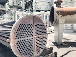
U-tube, removable bundle designs: The U-tube consists of straight-length tubes bent into a U-shape (Figure 2). Depending on the fluid outside the tubes, the bundle comes with tube supports or flow baffles along its length. The tube bundle assembly that fits inside the shell includes the tube-sheet, tubes, tube supports and flow baffles. For small heat exchangers, the shell can be a length of pipe that contains inlet and outlet connections and a flange at one end to insert the tube bundle. The other end of the shell comes with a cap or head. For large heat exchangers, the shell is a properly fabricated pressure vessel. This is to contain the fluid on the outside of the tube bundle. A head assembly is usually bolted to the shell flange to complete the heat exchanger. This contains the inlet and outlet connections for directing the fluid (usually liquid) into the tube bundle.
The head assembly contains one or more pass partitions. This also affects the tube-side heat transfer coefficient and pressure drop. The tube bundle should usually have tube supports along its length. When condensing vapor is a possibility, the provisions are needed for proper flow and drainage of condensate out of the shell. When a liquid circulates outside the tube bundle, flow baffles are necessary to support the tubes and direct flow across the bundle. In this case, the number and spacing of the flow baffles control the shell-side heat transfer performance and also its pressure drop. The nature of the U-tube construction allows for large temperature differences between the tube-side and shell-side fluids with the U-tubes expanding or contracting independently of the shell assembly. In addition, the tube bundle assembly is removable for easy and cost-effective replacement of the heat-transfer surface should a failure or leak develop in the bundle.
U-tube type heat exchangers have some limitations and disadvantages. First, because of the U-bends, the tube-side fluid/liquid always makes multiple passes down the length of the equipment. This may not be economical on close temperature approaches, and there might be high-pressure losses associated with it. The U-bend also prevents mechanical cleaning of the heat exchanger when the tube-side fluid/liquid is dirty or prone to scaling or fouling. U-bends may also be more susceptible to failures, cracks and problems, though these issues have been solved for many modern units.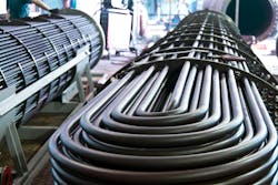
Straight-tube shell-and-tube designs: This type of unit is a common choice for handling heavy fouling fluid/liquids or scaling applications (Figure 3). The straight tubes allow for the removal of the head assemblies and mechanical cleaning. This feature is especially important if the tube-side fluid/liquid is prone to heavy fouling or scaling. In addition to having the capability for multiple tube-side passes, the equipment can be constructed for a single tube-side pass of the fluid/liquid through the unit. This means that 100% counter-current flow can be achieved between the tube-side and shell-side fluids. The fixed tube-sheet construction, however, does limit the ability to handle large temperature differences between the fluids.
Because the tube bundle and the shell assembly are not independent in this type of heat exchanger, any differential thermal expansion or contraction between the two will result in stresses being transferred to the joint of the tube and tube-sheet. The produced thermal loads/stresses can be sufficient to cause a break in the mechanical bond and, consequently, a failure. While the expansion joint or similar provisions can be incorporated into the shell to absorb the stresses, this is an expensive alternative and not desired. The expansion joints can be subject to fatigue of its own based on the thermal cyclic rate and operational parameters.
These have been special provisions with many requirements for maintenance and operation. They should only be used in special applications. As a rule of thumb, differences between the average fluid temperatures greater than about 35°C should be checked for excessive stresses. Even though the difference between average operating temperatures may not indicate a differential thermal movement problem, the heating up and cooling down from extreme operating/environmental temperatures may cause excess stresses at the tube-sheet interface. The bundle assembly is non-removable in most cases. There is no possibility for bundle removal in fixed tube-sheet equipment.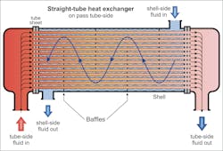
Fixed Tube-Sheet Heat Exchangers
This is the most commonly used heat exchanger in ordinary and conventional services. It typically has the lowest capital cost per square meter of heat-transfer surface area. Fixed tube-sheet heat exchangers consist of a series of straight tubes sealed between flat, perforated metallic tube-sheets. The straight tubes usually are mechanically rolled into a header at each end of the shell. The headers are welded/integral to the shell and act as both a tube-sheet and mounting flange for each of the tube-side heads. As a result of its welded construction, the fixed tube-sheet heat exchanger can accommodate high pressures, say over 70 Bar(g). There is no gasket or packing joint inside the shell, eliminating potential leak points. This equipment type is suitable for higher-pressure or risky services. However, because the tube bundle is not removable, the shell side of the heat exchanger (outside of tubes) requires chemical cleaning. The inside surfaces of the individual tubes can be cleaned mechanically after the channel covers have been removed. The fixed tube-sheet heat exchanger is limited to applications where the shell-side fluid is non-fouling. Fouling fluid/liquid should be routed through the tubes.
Floating Tube-Sheet and Floating-Head Heat Exchangers
A floating tube-sheet type is a removable bundle with a stationary tube sheet at one end of the unit and a floating (pull-through) tube sheet at the opposite end. The floating tube sheet is independent of the shell and fits inside the shell and head assembly diameters. To contain the shell-side and tube-side fluids at the floating tube-sheet end, a gasket or packing is usually used.
The floating-head heat exchanger provides all the advantages of a straight-tube unit without the disadvantages of the fixed tube-sheet type. This equipment type is relatively expensive and rarely used in ordinary applications. The ability of the tube sheet to move or float within the shell and head means that the equipment can handle large temperature differences without creating excessive stresses.
Hairpin Heat Exchangers
A variation of the single-pass shell-and-tube heat exchanger is the hairpin-type heat exchanger (Figure 4). This type is single-pass shell-and-tube equipment that has been folded in half, giving it a hairpin appearance. What distinguishes it from the traditional shell-and-tube exchangers are the end closures, which allow for thermal movements without expansion joints and the removal of tubes. This type is often used in special services. Examples are when there are solids in the stream, high-pressure services for tubes or high flow-rate ratios exist between tube and shell fluids.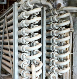
Plate-Type Heat Exchangers
These units have emerged as an alternative to shell-and-tube heat exchangers for many applications (Figure 5). They can help optimize thermal performance by enabling a number of close-temperature approaches and cross applications that previously were not economical or practical with shell-and-tube heat exchangers. They are compact, lightweight, efficient and easy to maintain. In its most basic form, a plate-type heat exchanger consists of corrugated plates compressed in a frame. They are available in many different models, types, configurations and constructions, including prime surface type and plate-and-frame designs, as examples. They come with either gasketed or welded construction.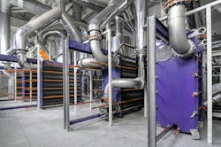
Plate-and-Frame Heat Exchangers
Fabricated from a series of channel plates that are pressed together to form a plate pack, these units come with holes at the corners of the plates to form a continuous passage or manifold. This subassembly distributes the heat-transfer media from the inlet of the heat exchanger into the plate pack for each of the fluids. The media then flow into the narrow channels formed by the plates. The gasket arrangement on each plate distributes the hot and cold media into alternating flow channels throughout the plate pack. Hot and cold media flow usually counter-current to each other.
The most common type of plate-and-frame heat exchangers are gasketed plate units.
Heat exchangers of this type include a series of channel plates that are mounted on a frame and clamped together. Each plate is made from pressable materials, such as stainless steel, and is formed with a series of corrugations. The most common pattern of corrugation is the herringbone or chevron pressed into each plate to produce highly turbulent fluid flows. The high degree of turbulence results in high heat transfer coefficients and keeps fouling to a minimum. In addition, the corrugations add rigidity to each channel plate. This allows the use of thinner plate material and improves heat transfer. Also included with each plate is an elastomer gasket. This gasket is used for sealing purposes and to distribute the fluids properly in the plate heat exchanger. Spaces between adjacent plates form flow channels for the hot and cold fluids.
Some of the benefits of a plate-and-frame heat exchanger include 100% counter-current flow, high turbulence and thin plate material, making it is a highly efficient device that typically yields heat transfer rates three to five times greater than conventional shell-and-tube heat exchangers. The design also is more compact than other heat exchangers.
However, high maintenance costs and operational difficulties have been reported for certain applications, requiring more frequent replacement of gaskets. In this case, chemical processing plants may opt for units that don’t need gaskets, such as printed circuit heat exchangers.
By carefully considering the appropriate heat exchanger design for their operating environment, chemical processing plants can minimize costs and boost efficiencies throughout their operations.
About the Author

Amin Almasi
rotating equipment consultant
AMIN ALMASI is a mechanical consultant based in Sydney, Australia. He specializes in mechanical equipment and offers his insight on a variety of topics including pumps, condition monitoring, reliability, as well as powder and fluid handling and water treatment.