Give your compressors a boost
The dynamics of a compressed air system can wreak havoc on the operations of individual compressors. Understanding these dynamics is essential if you are to succeed in improving the efficiency and reduce the operating costs of a compressed air system.
Before we get into the dynamics, though, let's look at how compressor controls work. Controls on each compressor use pressure to manage volume output and prevent compressor damage.
When compressor capacity exceeds demand, pressure increases. The controls respond to pressure changes within preset limits. In most systems, it is necessary to have more compressor capacity than required by the system at peak demand level (including short-term requirements created by intermittent users). The reasons for this are: system pressure will fall if the compressor capacity is less than the requirement, and precisely matching the air supply demand only occurs momentarily, if at all. Because peak demands are intermittent, managing output really means limiting compressor performance most of the time to maintain the desired pressure level. Depending upon the manufacturer and the type of compressor, compressor controls accomplish this using a variety of methods.
Diverse signal locations
- Compressor controls adjust airflow on pressure changes. Therefore, the location at which each compressor monitors pressure becomes critical to understanding its response and performance. Over the years, compressor manufacturers have relocated the compressor signal line for a variety of reasons. For example, reciprocating compressors, to minimize the impact of pressure pulsations, typically take the signal from a receiver that is downstream of the aftercooler. In contrast, centrifugal machines generally have a pressure sensor much closer to the compressor, so that the controls can detect and protect it from potentially destructive surge conditions.
Rotary screw compressors are the least consistent in terms of signal location. Their signals can be taken from the sump or after the separator, the minimum pressure valve or the aftercooler. The signal prevents over-pressuring the machine or over-powering the motor. The concern is that if the signal is located downstream of an accidentally closed block valve, the controls could respond to a lower system pressure -- and the compressor would essentially deadhead against the valve, thereby causing high internal pressures and high power consumption. Certainly, relief valves and other safety mechanisms can be used to minimize the risk and damage, but it is better and less costly to avoid such a condition.
Let's consider why these signal locations may not be optimal from a system point of view, and how the variety of locations complicates the process of optimizing efficiency.
Figure 1.
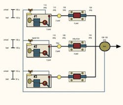
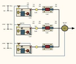
- The variety of compressor signal locations can cause a 3- to 7-psi misinterpretation of system pressure.
- Source: Compressed Air Challenge
Inaccurate interpretation
- Consider a rotary screw compressor with a closed block valve. When the compressor loads, its internal pressure increases and the signal will unload or modulate the machine. However, because it cannot deliver air to the system, the compressor will not have any impact on system pressure.
If the block valve is opened, the pressure in the compressor sump attempts to equalize with the lower system pressure. As this occurs, the pressure drop slowly dissipates, allowing the controls to read the system pressure more accurately and respond appropriately. Obviously, the pressure drop distorts the controls' reading -- the greater the pressure drop, the worse the distortion. While we can open the valve to eliminate the problem, the pressure drop in the system will cause the same problem to occur.
The variety of signal locations shown in Figure 1 can create a 3 psi to 7 psi misinterpretation of system pressure. More importantly, each compressor interprets the common system pressure differently, as shown in Figure 1. Note that Compressor No. 1 has a signal location on the sump after the separator, but before the aftercooler (shown as air-cooled). Despite having the same 110 psig discharge pressure as Compressor No. 2, Compressor No.1 gives a reading of 115 psig because of the pressure differential across the aftercooler. In reality, these two compressors will reach the unload pressure at virtually the same discharge pressure, even though the control bands are set at a reasonable cascade. This is why it is difficult to get multiple compressors to work together in a system. The problem is compounded when there are multiple compressors in multiple locations.
Figure 2.
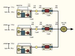
- Taking the signal after filters and dryers offers a number of important functional and efficiency benefits.
- Source: Compressed Air Challenge
Control band erosion
- Another major issue often overlooked is the impact of pressure drop on the control band.
For example, most compressors have an adjustable control range, which typically is preset at 10 psi between load and unload points. Examine Compressor No. 2 in Figure 1. The pressure drop between the signal location and the plant header is 6 psi. Because the compressor's set point is in the trim position running load/no load, the effective control band is about 4 psi.
Here's why: When the compressor reaches its unload set point of 110 psig based on the signal, it unloads. Because there's no flow from the compressor, the 6 psi pressure drop immediately disappears and the pressure at the signal location equalizes with the system's 104 psig. However, when the pressure drops to the load set point of 100 psig, the flow reestablishes the 6 psi differential and the pressure at the signal location immediately jumps to 106 psig (although the system pressure is still at 100 psig).
As the header increases by 4 psi, pressure at the signal reaches the unload set point of 110 psig and the compressor unloads again. So, there is an effective pressure range of 4 psi while depressurizing (104 - 100 psig) and an effective pressure range of 4 psi while pressurizing (106 - 110 psig). The speed at which this cycling occurs can be predicted by comparing the compressor capacity to system storage. However, it is important to understand that control band erosion is a major contributor to rapid cycling in air compressors. This causes inefficiency, lubricant carryover and reduced air-end life.
In the circumstances described above, the most common strategy is to put the compressors into a modulation control mode. Modulation allows each compressor to be partially loaded and, from a practical standpoint, only the control bands determine the pressure at which the compressors reach full load. However, system efficiency will suffer because the modulation significantly inhibits a rotary screw compressor's efficiency. For example, at 40% of its rated flow capability, the compressor still requires more than 80% of its rated power. An even more costly factor is that, in full modulation control, the compressor never unloads -- and, therefore, is never turned off except by manual intervention. This results in more units than required running modulated and, as the demand drops, the compressors become less and less efficient. Without unload and sump depressurization occurring, it is difficult to determine just how much capacity is being delivered to the system. With centrifugal compressors, this condition will cause the compressors to blow off, which is even more inefficient.
The solution
- A more functional and efficient solution is to install a common signal line for compressors (Figure 2). A signal taken after the filters and dryers allows the compressors to respond directly to the header or storage pressure. It also retains the ability to unload the compressors and use the automatic start and stop to turn them off when demand drops.
A downstream signal location offers many benefits, including:
Critical issues
A pressure drop across the cleanup equipment still exists, but the controls do not read it. This means the control bands must be adjusted to provide the desired header or storage pressure while not over-pressurizing the compressor at the sump or discharge.
In addition, if the control bands are not adjusted to maintain the existing header or storage pressure, the energy consumption may increase because of higher pressures. (Higher pressures mean more compressor power consumption.) However, the system flow also will rise unless a pressure flow control (modulating a flow control valve to a pressure set point) is used to maintain a constant header pressure.
Closing a block valve anywhere between the compressor discharge and the signal location means the compressor will deadhead against the valve and the controls will not allow unloading. This over-pressurizes the sump, which lifts the safety relief valve and discharges hot lubricant. It also could over-amp the motor.
Only knowledgeable, experienced compressor technicians should set up compressors with downstream signals. The pressure in the sump or discharge and power draw on the motor should be monitored when setting the downstream controls to confirm that the compressor is operating within its design parameters.
For safe operation, tag or lock the block valves on the compressor discharge and train the operators not to shut the valves when the compressor is running or capable of running.
Connect the downstream signal to the existing signal with a two-position valve. This allows either signal location to be used and prevents both signal locations from being turned off at the same time.
Install an extra pressure switch, with its signal on the compressor sump, in series in the unload circuit. Set this switch to unload the compressor at the rated pressure at the sump or at a pressure that protects the motor.
Consider installing a digital ammeter and pressure gauge for each compressor to provide accurate readings of operating conditions. Use the pressure reading to monitor total pressure drop from compressor discharge to the system.
Coping with complex systems
Another benefit of automation is the ability to rotate or sequence different compressors so running conditions can be maintained or wear can be equalized. This is particularly important in larger systems, where the demand varies significantly, or in systems with different compressor technologies.
For example, a larger system may rely on centrifugal compressors for base loads, with these rotated on a periodic basis to maintain condition, while rotary screw or reciprocating compressors are used to accommodate any daily demand variations.
Using pressure flow controllers in systems with variable air demand can provide additional savings by allowing stored air to support intermittent peaks in demand while managing the compressors to support the average demand.
We strongly recommend working with an experienced system designer to ensure that automation is applied properly.
Proper application of controls minimizes the compressor power at any point by more closely matching the operating supply capability to the demand. Knowledge of the issues involved in coordinating compressor operations will allow you to manage the supply system as efficiently as possible.
Dean E. Smith is manager of system design and auditing for Air Science Engineering, a division of Enpro Industries, Chandler, Ariz.


