The purpose of pump piping is to provide a conduit for the flow of liquid to and from a pump, without adversely affecting the performance or reliability of the pump. However, many pump performance and reliability problems are caused or aggravated by inadequate system piping.
This article, largely based on the latest International Standards Organization/ Hydraulic Institute (ISO/HI) draft standard, "Pump Piping for Rotodynamic (Centrifugal) Pumps," outlines the methodology required to ensure optimum piping leading to and from a centrifugal pump.
Consider various factors when selecting how to guard against low flow, Andrew Sloley says in this month's Plant Insites column.
Select the Right Centrifugal Pump
Consider a wide variety of design and other issues.
Seal Off Centrifugal Pump Problems
Paying proper attention to seals can improve pump performance and life.
Take a Different Look at Centrifugal Pumps
An unconventional assessment can provide insights for effective control.
Suction piping
The function of suction piping is to supply an evenly distributed flow of liquid to the pump suction, with sufficient pressure to the pump to avoid cavitation ," and related damage ," in the pump impeller. An uneven flow distribution is characterized by strong local currents, swirls and/or excessive entrained air.
The ideal approach is a straight pipe, coming directly to the pump, with no turns or flow disturbing fittings close to the pump. If the suction piping fails to deliver the liquid to the pump in this condition, a number of pump problems can result, including:
Noisy operation.
Random axial load oscillations.
Premature bearing or seal failure.
Cavitation damage to the impeller and inlet portions of the casing.
Occasional damage from liquid separation on the discharge side.
Discharge piping
Discharge piping flow characteristics normally will not affect the performance and reliability of a rotodynamic pump, but a few exceptions exist in situations in which:
High-energy pumps might be sensitive to flow-disturbing fittings mounted close to the pump discharge flange.
Sudden valve closures might cause excessively high water-hammer-generated pressure spikes to be reflected back to the pump, possibly causing damage to the pump.
Discharge piping might affect pump starting, stopping and priming.
The discharge piping configuration also might alter any discharge flow recirculation that might extend into the discharge piping at very low flow rates. This could have a small effect on the head developed by the pump.
Mechanical considerations
Two of the more common detrimental effects from pump piping are the excessive nozzle loads the piping can place on a pump and the excessive nozzle loads that unsupported equipment such as valves or vertical inline pumps can place on the piping. Excessive nozzle loads can be caused by thermal expansion of the pipe, unsupported piping and equipment weight, and misaligned piping.
Proper piping and pump layout design and analysis prior to installation of a system are absolutely essential to the life and reliability of a pump. These steps can help ensure nozzle loads remain below acceptable limits for installed pumps. A properly supported piping system minimizes field adjustments during installation, saving both time and money.
Nozzle loads affect pump operation in various ways. At low levels, the effects might be insignificant. At high levels, nozzle loads can contribute to:
Coupling misalignment, which can lead to heat buildup in bearings and decrease bearing life; in severe instances, fractures within the pump case; decreased coupling life; increased noise and vibration levels; and breakage of the pump shaft.
Shaft movement, which can lead to reduced mechanical seal life.
Fatigue or failure of the shaft.
Catastrophic structural failure of pump hold-down bolts/supports and pump nozzles.
Pump casing gasket leaks.
Pipe-to-pump flange leaks.
Decreased mean time between repair or failure.
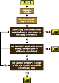
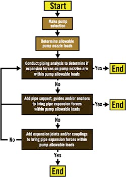
The ISO/HI Pump Piping Work Group developed the flow chart shown as Fig. 1, which gives the methodology that should be followed to avoid these types of potential mechanical pump problems.
Figure 1. Flowchart for use of ISO/HI Pump
Piping Standard (Mechanical Considerations)
By following the flowchart methodology, chemical plants can avoid many piping-related mechanical pump problems.
Hydraulic considerations
Suction piping. In general, pumps should have an uninterrupted and unthrottled flow into the inlet (suction) nozzle. Flow-disturbing fittings should not be present for some minimum length. Flow disturbances on the inlet side of the pump can lead to
Deterioration in performance.
Damage to the impeller and shortened impeller life (especially with high-suction-energy pumps).
Shortened mechanical seal life.
Shortened bearing life.
Isolation valves, strainers and other devices used on the inlet (suction) side of the pump should be sized and located to minimize disturbance of the flow into the pump.
The most disturbing flow patterns to a pump are those that result from swirling liquid that has traversed several changes of direction in various planes. Liquid in the inlet pipe should approach the pump in a state of straight, steady flow.
When fittings such as "T" fittings and elbows (especially two elbows at right angles) are located too close to the pump inlet, a spinning action or "swirl" is induced. This swirl could adversely affect pump performance by reducing efficiency, head and net positive suction head (NPSH) available. It also could generate noise, vibration and damage in high-suction-energy pumps.
It is recommended that a straight, uninterrupted section of pipe be installed between the pump and the nearest fitting. This should follow the minimum straight pipe length guidelines listed in the ISO/HI draft standard, which range from:
One to eight pipe diameters (for low suction energy/low specific speeds).
Three to 16 pipe diameters (for high suction energy/high specific speeds).
The specific straight pipe length recommendation depends on the type of fitting(s) and pump. Generally, high-suction-energy pumps have suction nozzles greater than 10 inches (in.) at 1,800 revolutions per minute (rpm), and greater than 6 in. at 3,600 rpm. High specific speed starts above a value of 3,500. If the minimum recommended pipe lengths cannot be provided, flow-straightening devices should be considered.
In addition to the minimum required lengths of straight suction pipe, it is equally important that the NPSH margin ratio (net positive suction head available/net positive suction head required [NPSHA/NPSHR]) guidelines listed in the HI standard on NPSH margin (ANSI/HI 9.6.1) be followed.
These NPSH margin ratio guidelines are dependent on the application and range from:
1.1 to 1.3 for low-suction-energy pumps.
1.3 to 2.5 for high-suction-energy pumps.
It is especially critical for plants to follow these NPSH margin recommendations for high-suction-energy pumps. By doing so, they avoid excessive pump noise, vibration and/or damage, particularly in the region of suction recirculation.
Discharge piping. Pipe fittings mounted close to the outlet (discharge) flange normally will have a minimal effect on the performance or reliability of low-energy rotodynamic pumps. On the other hand, high-energy pumps can be sensitive to flow-disturbing fittings mounted close to the pump outlet flange. These fittings could result in increased noise, vibration and hydraulic loads within the pump.
According to HI, pumps with specific speed values below 1,300 that generate more than 900 feet of head per stage are considered to be high-energy pumps. The differential head value for high energy drops from 900 feet at a specific speed of 1,300 to 200 feet at a specific speed of 2,700.
It is recommended that high-energy pumps meet the minimum straight discharge pipe length requirements in the ISO/HI pump piping draft standard (one to four pipe diameters). The specific straight pipe length recommendation depends on the type of fitting(s) downstream of the pump.
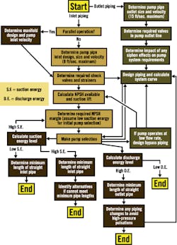
The ISO/HI draft pump piping flowchart for hydraulic considerations is presented as Fig. 2. Although the flowchart is complex, it is critical that plants follow its methodology to ensure reliable pump performance, especially for high-suction-energy and high-energy (discharge) pumps. Again, each of the items in this flowchart represents a section in the ISO/HI draft standard.
Figure 2. Flowchart for use of ISO/HI Pump
Piping Standard (Hydraulic Considerations)
To ensure reliable pump performance, particularly for high-suction-energy and high-energy pumps, chemical plants should follow the methodology shown here.
Conclusion
Although it often is not given the attention it deserves, the design of the system piping attached to a centrifugal pump can greatly influence the pump's performance and reliability. However, most of the published literature currently available on this subject provides only broad general guidelines or is limited in scope. The new pump piping standard being developed by the joint ISO/HI Pump Piping Work Group should go a long way toward filling this critical void. The document is in the balloting stage. CP
Budris is a consulting engineer in Geneva, N.Y., specializing in the selection, application and troubleshooting of pumps and pumping systems. Most recently, he served as director of product development for the Industrial Pump Group of ITT Industries, Seneca Falls, N.Y. He is chair of the ISO/HI Pump Piping Work Group. Contact Budris at [email protected].


