Getting the most out of your equipment is becoming more and more important in the chemical industry. Lean staffs, high energy costs, and market pressures are driving manufacturers to carefully look at the ubiquitous pump.
Equipment manufacturers formerly devoted to product development and distribution of process equipment are transforming into enterprises that provide services throughout the product life cycle. This trend has accelerated in more recent years as equipment users refine internal functions and increasingly outsource activities.
Today, the rapidly expanding service industry touches virtually every element of the equipment life cycle. What is driving this evolution? Owners have recognized that the overall cost of ownership is much greater than the acquisition cost — decisions made during the acquisition phase can dramatically affect lifetime ownership cost.
In the pump industry we recognized this a result of a joint effort between a major chemical manufacturer and one of Flowserve’s heritage companies, Durco International. That research was focused on chemical process pumps (ASME /ANSI B 73.1) and showed that the initial acquisition cost was as low as 5% of the life cycle cost (LCC). The LCC is not the sum of its parts.
In 2001 the Hydraulic Institute and Europump published a comprehensive guideline for evaluating LCC for pumps. As one would expect, these costs include design, purchasing, installation, operation and maintenance. Also included was the disposal cost, which has become more relevent today than ever before.
Although users are beginning to recognize the importance of LCC, how the various LCC elements interact with each other is not well understood. For example, optimizing installation costs could have a negative effect on equipment maintenance expenses. What is required is a comprehensive holistic approach to LCC where the optimization process is tailored for specific business variables and objectives.
This means looking at all components of LCC as a whole and considering their interactions and conflicts. Pump reliability is not defined by identifying the least reliable component. A seal, with a service life of one year, may leak after a few months if a suction hose leaks; the two parts are linked.
In a new installation most of the components affecting LCC can be considered as variables to be holistically optimized. For existing installations however, these factors are often fixed. The solution is to break down the LCC into two segments: LCC to date and future LCC.
Generally, the evaluation of the future LCC can be simplified by considering only the most significant costs: operation, energy and maintenance.
False perceptions
A common misconception is that energy costs are synonymous with pump efficiency. This isn’t the case in most situations. Typical pumping systems utilize a control valve to regulate flow rate to the desired amount. Although it’s necessary for a control valve to be partially closed at the design condition to maintain flow control, sizing the control valve for an excessive pressure drop is common — usually as a result of compounded design safety factors.
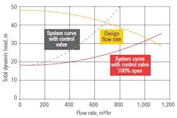
Figure 1 illustrates a pumping system designed to deliver 680 cubic meters per hour.
Figure 1. The control valve is sized for a 17-meter pressure drop at design flow rate.
To maintain the design flow rate a control valve was selected with a 17-meter pressure drop. Additionally, when fully opened the control valve would permit 150% of design flow rate in the system. A properly-sized pump could operate with a control valve sized for a 3-meter pressure drop at design flow.
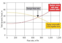
The overcapacity of the pumping system and inappropriate design of the control valve increased energy costs by more than 50%. Taking advantage of this savings requires the pump impeller diameter to be reduced as shown in Figure 2.
Figure 2. Optimize impeller and re-size control valve for the lowest operating cost.
The argument often made for using an undersized control valve is that it allows the system to operate as intended even if the pump deteriorates. While this is true, there is an effect on energy cost. Additional attention to maintenance of the equipment would easily pay for the reduction in energy cost and would dramatically reduce total costs.
For comparison Figure 2 also illustrates the effect of a higher efficiency pump (i.e., 80% versus 75% efficiency). The higher efficiency pump decreases energy costs by 7%; while not insignificant, this example illustrates the importance of considering the total system instead of focusing only on pump efficiency.
Although efficiency is vital, in an existing installation, matching the impeller to the system curve is where the payoff is (Figure 2). Trimming the impeller and re-balancing are relatively inexpensive and can be performed during routine maintenance. In many cases “right-sizing” the impeller diameter delivers an added benefit of improved reliability and lower vibration.
Variable frequency drives (VFDs) are often proposed as a means of energy reduction. In systems with widely varying flow rate requirements, and where system friction is a significant component of the system head, VFDs offer a viable solution for reducing LCC. In some applications VFDs also can eliminate the need for control valves and their associated maintenance expense. Unfortunately, drives often involve significant installation and set-up costs that may offset any impact on savings. Other costs associated with VFDs should be considered.
For example, conditioning of the power supply may be required to ameliorate high frequency harmonics. The type of process control is important. There are differences between a flow rate-regulated system and a flow quantity-regulated system. Most pumps are flow rate-regulated with a control valve or VFD. Some pumps are quantity-regulated by means of timers or level. Examples of these systems are municipal potable water systems that supply stand tanks and waste treatment lift pumps. In a quantityregulated system energy consumption is primarily affected by pump and motor efficiency; piping system changes to existing installations are usually impractical.
Comparing options
Maintenance costs and energy costs are often interrelated. Hydraulic experts have published numerous papers demonstrating the relationship between pump selection and reliability. They show that pump flow rate, speed, impeller diameter and suction energy (SE ) all affect reliability (Figures 4-7 and the SE sidebar). These four factors can be quantified using reliability factors whose values range between 0 (very poor reliability) and 1 (excellent reliability).
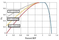
Figure 3 shows how Fo, the reliability factor, is related to the best efficiency point (BEP ). At BEP the reliability factor is 1 (excellent), whereas at low flow rates the reliability factor decreases, as expected. Relatively speaking, smaller pumps are more robust and can tolerate low flow rates better than larger pumps.
Figure 3. Smaller pumps are more reliable if demand roams below the design flow.
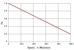
Figure 4 shows a straight-line relationship between the speed and reliability. Although pumps are designed to operate up to their maximum design speed, their reliability is greater at reduced speeds. The speed reliability factor (FN) of Figure 4 shows that a pump operating at half of its maximum design speed (e.g., 1,750 rpm operating speed for a 3,500 rpm maximum design speed pump) is 3 times as reliable (FN of 0.6 versus 0.2).
Figure 4. Not surprisingly higher speed pumps sacrifice head for degraded reliability.
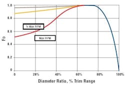
The impeller diameter, compared to the maximum trim, significantly affects reliability. Observations of pressure gauge fluctuations for pumps with maximum diameter impellers show much higher pressure spikes than for pumps with trimmed impellers. This is especially true for higher speed pumps. These pressure spikes are felt by the pump, its bearings, and via shaft deflections, by the mechanical seals. The impeller diameter reliability factor FD of Figure 5 reflects this observation. To account for different pump designs the diameter of the impeller (the trim) has been expressed as a % of the amount that the impeller can be cut.
Figure 5. The best reliability is achieved by running the largest trim; reducing trim to achieve energy efficiency might have a hidden maintenance cost.
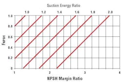
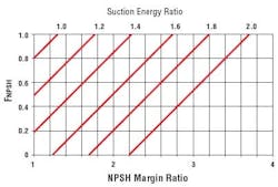
The net positive suction head (NPSH) margin and the SE ratio also affect pump performance and reliability. Figure 6 illustrates the relationship between reliability (FNPSH), NPSH margin ratio, and SE ratio. Suction Energy is a measure of the potential for damaging suction recirculation whereas NPSH Margin Ratio (NPSH available/NPSH required) is a measure of the ability to suppress suction recirculation damage (see sidebar). Most process pumps are designed with relatively low values of Suction Energy and have values for FNPSH of 1.
Figure 6. A powerhouse application shows pumps operating at a wide range of conditions.
These reliability factors can be used in evaluating the benefits of making changes to a pumping system. In comparing options for a particular application the “relative reliability index” or RI , should be evaluated. Use the following equation based on the factors from Figures 3-6:
RI = Fd × Fn × Fq × FNPSH
Because of the nature of the individual factors, the RI will be between 0 and 1 and will be less than these factors. In most cases reducing energy consumption also lowers maintenance expense; however this is not always the case. For example, reducing impeller diameter can increase recirculation in the suction; this leads to pump damage (Figure 5).
Although reducing energy consumption in pumping systems may seem straightforward, it can be a complicated task. Energy savings are often exaggerated by using simplified analysis found in the literature. A thorough understanding of the hydraulics of the system and the plant needs are necessary. Maintenance departments and project engineering ultimately serve production.
A telling example
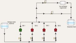
Inspection of one of the pumps in a complex system (Figure 6) revealed extensive suction and discharge recirculation which damaged the impeller. This led to a suspicion of problems with the NPSH. Additional study revealed that the pump had a very high SE ratio and a relatively low NPSH Margin Reliability Ratio (Figure 7).
Figure 7. The closer the NPSHA is to the NPSHR, the lower the reliability.
Testing of the pumps identified significant pump deterioration and a wide variation in performance capabilities. Because these pumps operated in parallel, one of more of the pumps probably operated very near shutoff. Table 1 summarizes the financial and reliability aspects for each option evaluated for the pumphouse:
Option 1: Identical replacement pumps with improved characteristics and materials (to stainless steel from cast iron). This was the option ultimately selected.
Option 2: Replacement pumps with larger impeller pumps with upgraded materials. This option was rejected as a result of an even higher SE ratio.
Option 3: Install one large pump with a VFD to replace the existing four pumps. This option provided the most energy effective and reliable solution, however the high equipment and installation costs resulted in an unacceptable payback period.
Option 4: Continue with the existing pumps — this was the baseline.
Option 5: Replace the existing 4×3×10 pumps with 6×4×10 pumps. Due to differences in hydraulics of these pumps they would produce significant energy and reliability savings. The operator rejected this option because the performance curve of the pump is very flat, creating the risk of running one of more of the pumps at shutoff during various operating scenarios.
Figure 8. Operating near shut-off shortens the MTBF of a pump.
As the example demonstrates, a thorough knowledge and understanding of pumping systems is required to effectively undertake pumping system analyses. Recognizing a potential value to its customers, Flowserve has established a team that provides LCC optimizing services for existing installations. In one example, the team conducted analyses of over 140 pumping systems and identified $2.3 million in annual savings.
The future is bright
As leading equipment users in the process industries continue to see the economic benefits of optimizing existing pumping systems, there will be a growing demand to use this strategy to drive out costs and improve equipment reliability. The continual improvement of modeling software will aid in implementing a total cost of ownership perspective. CP For more information on pump lifecycle costs, please refer to www.flowserve.com.
|
NPSH Margin Reliability Ratio is a safety factor for pump NPSHrequired. S = N(Q)0.5/NPSHR0.75 The Hydraulic Institute recommends a suction speed of less than 8,500 at low flow, however, speeds up to 11,000 have been used. A quick fix for a high suction speed with an existing pump installation may be a recirculation line or VFD. Unfortunately, it may be necessary to consider a pump change such as multiple pumps or departing from centrifugal pumps altogether. Suction speed fixes the impeller type; and, changing the impeller may very well change the pump characteristics and power draw requiring a new pump. Suction Energy (S.E.) is a relatively new term related to suction speed. It is easily calculated. For example, with S = 9,000, shaft speed (N) = 3,550 rpm, an impeller diameter of 6 in. (De), and a specific gravity of 1.0 (Sg) suction energy can be calculated according to the following equation: S.E. = De × N × S × Sg = 6 × 3,550 × 9,000 × 1.00 = 192×106 A value above 160×106, for a typical pump is too high. For additional information on suction energy and suction speed and how they relate to NPSH and speed, refer to http://www.gouldspumps.com/cpf_0008.html, http://www.lawrencepumps.com/newsletter/news_v01_i5_oct.html, http://www.gouldspumps.com/cpf_0005.html, and http://www.chemicalprocessing.com/articles/2004/187.html. |
Tom Carsten is the director of alliance development for Flowserve in Dayton, Ohio, and Barry Erickson is the key account manager for Flowserve serving Eastman Kodak in Rochester, N.Y.; e-mail them at [email protected] and [email protected].
