Piping Geometry: Grasp Line Layout
When do you slope a process line? When is self-draining required? How does self-draining contrast with self-venting? How do these differ from no pockets? Such issues seem to confuse many engineers. So, let's delve into line geometry.
Convenience and cost of piping runs set the overall geometry, except when special process requirements impose specific layouts. Piping designers rarely consider process needs, except for line sizing based on pressure drop or velocity.
At a minimum, the line geometry must account for startup and shutdown.
Filling a liquid line requires venting gas or air out. Draining such a line demands getting the liquid out of low points. For piping designers, the easiest approach is to add high-point vents and low-point drains. However, for some specific services, you many want to avoid extra valves and connections.
Liquid lines also may suffer from vapor pockets. These may block lines, preventing liquid flow. Under other conditions, a sudden shift of a vapor pocket can create slug flow — damaging equipment and creating operating or safety problems.
Many process vapor lines may accumulate condensation. Liquid also may get into lines due to upsets and entrainment from towers or separator drums. The accumulation may not be apparent until serious unit upsets occur. So, rather than depending upon subtle signals and operator draining of low points, configuring piping to prevent accumulations may make sense.
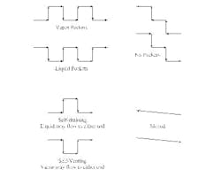
As mentioned, basic pipe layouts often include high-point vents and low-point drains to deal with startup, shutdown and operating upsets. Experienced piping designers ensure the drains are easily accessible. Figure 1 shows lines with both vapor pockets and liquid pockets.
If process requirements mandate, the piping will feature a self-draining, self-venting, no-pocket or sloped layout (Figure 1).
Self-draining lines may have a high point, so liquid can flow in either direction away from that point. Self-draining lines are relatively common in many plants. The intent is to prevent liquid slug formation and to keep liquid in vapor lines from increasing pressure drop.
Self-venting lines may have a low point, so vapor can flow in either direction away from that point. These are less common than self-draining lines because they still require a liquid drain.
No-pocket lines have a layout that allows liquid to drain down and vapor to vent up, obviating vents or drains. Process or startup and shutdown conditions may set the line sizing. If the liquid and vapor flow in the same direction during normal operation, very little extra care is needed. However, if the vapor and liquid must flow in opposite directions during operation, line sizing must keep velocities low enough that holdup doesn't cause slugs of liquid or vapor.
Self-draining, self-venting and no-pocket lines all may include level spots. Such a spot, especially in line sizes above 3 in., will drain most liquids without difficulty.
Continuously sloped lines are least common. These lines may be both sloped and no-pocket or sloped and self-draining; sloped and self-venting is unusual. The typical purpose of a sloped line is to keep velocity high for any liquid in vapor piping — e.g., to reduce residence time, keep fouling potential down or prevent solids' deposition. Typical slopes start at 1 in./8 ft (roughly 1%).
Sloped lines can be expensive. They require special accommodation in piperacks and are more difficult to install. In general, avoid a sloped line unless there's a clear reason to use one or a significant risk of a liquid pocket sticking in a small line.
Apply extra care to orifice and other head meters. Such flow meters impose a pressure drop by partially blocking the line. If enough liquid is present to justify self-draining or no-pocket lines, strongly consider eccentric orifices to prevent liquid pocket formation. Also, think about orifice plates with vapor venting holes.
Experienced piping designers consider such issues. However, by knowing when a particular geometry is required, you can help ensure the proper selection of a line layout.