Turbo-compressors are flexible and efficient, and have a wide range of application. Evaluating and purchasing such a machine should involve a comprehensive optimization process. Otherwise, the turbo-compressor may not meet desired targets for performance, reliability, maintainability, availability, commercial terms or power requirements. So, this article will look at factors to consider in an optimization.
LOCATION
An important decision for every turbo-machine is whether it should be located indoors or outdoors. At first glance, an indoor installation seems safer, more reliable and better. However, design and operating experiences suggest examining an outdoor installation first. It can make operation and maintenance much easier, and cost far less.
An indoor installation can pose conflicting requirements for enclosure design, noise control, the heating/ventilating/air conditioning (HVAC) system, foundation and support design, and piping arrangement, as well as access for various maintenance activities and cranes. This could result in an extremely costly system and enclosure.
In many chemical-processing projects, the turbo-compressor is ordered based on indoor installation, assuming future design of an enclosure for noise control and protection (with overhead crane, HVAC, proper area classification, etc.). To keep costs down, the enclosure volume should be minimized — however, this compromises access and other requirements. The heat-generation calculation and proper ventilation usually are complex issues. Most importantly the access requirements for installation and major overhaul could be problematic. An indoor installation also introduces various health, safety and environmental issues.
That’s why I generally recommend an outdoor installation, initially without a shelter. Base required noise protection on an initial noise study, include an acceptable value (with a proper margin) in the vendor scope, and allow the vendor to suggest some machine-localized noise protection. My experience indicates an 83–85-dB noise limit could be a good range for the start. Use suitable mobile cranes for all maintenance (routine, overhaul, etc.). Later on, installation of a shelter (preferably a removable one) will improve the package’s reliability. Of course, an outdoor installation isn’t always best but certainly consider it first.
DESIGN AND MECHANICAL ISSUES
Factors to check include inter-stage pressures, auxiliaries, coupling selection, piping and auxiliary vessels, and provisions for condition monitoring.
Inter-stage pressures. Optimization requires considering the performance and investment for both the compressor and the inter-stage facilities (heat exchangers, drums, etc.). If both compressor and inter-stage facilities are in the vendor scope (the package design), it’s best to leave optimization to the vendor. However, in the majority of cases, the inter-stage facilities are supplied separately; the compressor vendor’s suggested inter-stage pressures for the compressor alone may not be justified and often aren’t optimum. So, as a practical matter, determine the inter-stage pressures (identified at the basic design phase) by proper optimization. Inter-stage pressures also may increase during different operating scenarios. Approximate pressure-drop values for inter-stage facilities are:
• around 0.5–1.5% of the pressure for the drums and vessels; and
• approximately 0.70–1.5 bar for the inter-cooler and after-cooler.
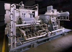
Auxiliaries. The oil system should include (at least) two oil pumps, both sized for 20% extra oil flow, dual removable-bundle shell-and-tube oil coolers (alternatively, plate exchangers or air-coolers), double (duplex) oil filters with removable elements and stainless steel piping.
For cooling water systems (particularly the electric-motor cooling water system, the converter cooling system, etc.), first calculate the generated heat and then adjust the temperature rise. To optimize the selection of centrifugal cooling-water pumps, pay special attention to the operating curve slope, ensuring you can get a continuous rise to the shutoff and a proper shutoff pressure. Some extra flow margin is necessary for reliability and to allow the machine to cope with situations other than normal operation, overload and future expansion (if applicable).
Figure 1. A turbo-compressor usually requires extensive auxiliaries. Source: Siemens.
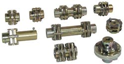
Figure 2. Couplings come in a wide variety of types.
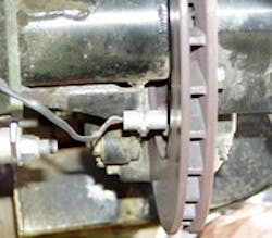
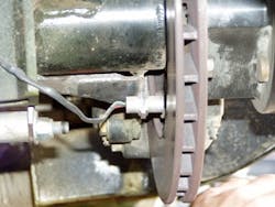
Auxiliary vessels (pressure vessels, separators, filters, etc.) located in the vicinity of a turbo-compressor can be subjected to vibrations and shaking forces. For auxiliary fixed equipment, provide a proper support (such as a skirt support); avoid leg-type or other relatively flexible supports.Adhere to good engineering practices for the vessels: • For all connections except small ones, use a WN (welding neck) joint. For small connections (say, below 2 in.), specify an integrally forged LWN (long welding neck) joint. • Insist upon full-penetration welding of all pressure and integral parts. • Specify nozzles self-reinforced with lip for critical applications to make “100% radiography” possible and reduce the stress concentration. If necessary, carry out a low-cycle fatigue analysis following the procedure described in the ASME Pressure Vessel Code, Section VIII, Division 2, Appendix 5. Stress-concentration and proper safety factors can decrease the cyclic stress limit to around 20 MPa peak-to-peak. Take special care with any vessel having a wall thickness greater than 50 mm. In many cases, the auxiliary equipment and vessels (drums, separators, filters, heat exchangers and the like) have caused delivery delays for the turbo-compressor package. So, carefully review the following:• material selection;• attachments and supports;• nozzles and nozzle orientation; and• internal piping and connections.Condition monitoring. For a complex unit like a turbo-compressor, condition monitoring can be particularly cost effective, lowering maintenance expenses and reducing risks of accidents —if the necessary items to identify malfunctions at an early stage are installed. I suggest monitoring the following:• casing vibration (it’s optimum to use both velocity transducers and accelerometers);• rotor vibration;• gas discharge temperature and pressure;• temperature of critical components and sections such as bearings and the cooling medium system; and• flow, pressure, temperature, etc. of lubrication oil.Figure 3 shows an example of a monitoring sensor for a turbo-machine.Figure 3. Adequately monitoring the condition of a turbo-machine can provide significant benefits.
A small-or medium-size turbo-compressor should be delivered fully fabricated as a single skid-mounted package. For a large turbo-compressor, it’s better to get the machine prefabricated in several skid-mounted packages. Each turbo-compressor casing (with gear unit, if any) should be mounted on a heavy-duty skid. The driver usually is delivered separately. I also recommend, as a first option, to ask the vendor to offer all site supervision work at a fixed price.
AMIN ALMASI is a rotating equipment consultant based in Brisbane, Australia. E-mail him at [email protected].
About the Author
Amin Almasi
rotating equipment consultant
AMIN ALMASI is a mechanical consultant based in Sydney, Australia. He specializes in mechanical equipment and offers his insight on a variety of topics including pumps, condition monitoring, reliability, as well as powder and fluid handling and water treatment.


