Processing Equipment: Nix Nozzle Nightmares
Modifying the internal layout of vessels can prompt unexpected problems. For example, after one plant switched the existing trays in a steam stripper from one-pass to two-pass in a quest for higher capacity, the tower didn’t work correctly. Several different problems seemed to occur as operators changed operating pressures as well as steam and product rates in an attempt to make the unit work.
[pullquote]
In general, at rates equal to the flow capacity of a single-pass tray, the system would work if steam flow rates weren’t too high. In contrast, at high liquid rates and high steam rates, the tower would flood. Achievable capacity was roughly 70% of the rate before the modifications, not the 130% intended by the project — which, quite correctly, was considered a failure.
Two-pass liquid trays increase tray capacity by splitting the liquid flow in half. Reduced liquid rates on each tray section decrease weir loading, diminish downcomer pressure losses and cut tray pressure drop. Yet, in this case, the modifications failed to deliver even the same capacity.
Preliminary evaluation of the unit operation didn’t clearly identify any reason for the capacity loss. Review of the tray design showed the trays should have worked. The fact they didn’t indicates two main areas to check: 1) whether process conditions significantly differ from those expected; and 2) whether the trays as installed aren’t what they should have been. Troubleshooting equipment configurations can be difficult on an operating unit. Unless the unit is shut down and physically inspected, what’s in the column may remain uncertain.
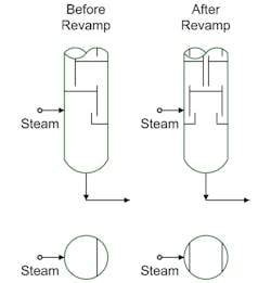
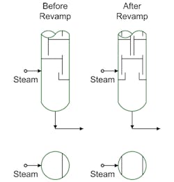
Figure 1 shows both the original and revamped bottom section of the column. Pay specific attention to the steam injection. Field inspection revealed that, while the trays had been changed, the external piping hadn’t been modified. The steam nozzle was putting the steam into the downcomer on one side of the tower.
Figure 1. Revamp, which involved switching from one-pass to two-pass trays, cut capacity instead of increasing it.
Steam entering the downcomer reduced its capacity, causing liquid to back up onto the tray above. At rates below about 70% of capacity, the downcomer had enough volume to still allow for vapor/liquid disengaging. At higher rates, the tower flooded.
The revamped unit actually suffered two problems due to nozzles. The second stemmed from the liquid feed nozzle also not being modified or relocated. All the liquid feed was entering on one side of the tower.
Either problem could prompt flooding of the tower. However, only the steam-nozzle problem was seen because it caused the tower to flood first.
So, an effective solution requires further work both at the tower liquid feed (top of the tower) and the tower vapor feed (bottom of the tower).
I have observed other issues with nozzles, including having:
• a feed nozzle in the center downcomer when trays are switched from one-pass to two-pass. This occurs if the nozzle is rotated 90° from the tray alignment line;
• liquid-level measurement nozzles in unusable locations because of changes in internal baffles or collectors; and
• non-usable nozzles after installing strip-lining inside the tower and not cutting holes in the lining for the nozzles.
When modifying vessel internal arrangements, ensure that external feed, product and instrumentation connections end up in the correct locations.
ANDREW SLOLEY is a Chemical Processing contributing editor. You can email him at [email protected]


