Prevent Paired-Pump Problems
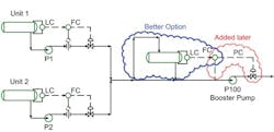
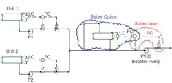
[pullquote]The centrifugal booster pump was vibrating and running hot. The pump took liquid from two sources and pumped it to a third unit. Figure 1 shows the original pump installation — as well as equipment added later and a better option, as we’ll discuss.
The original plant concept called for initially installing two matching modular units, Unit 1 and Unit 2, with a third identical unit, Unit 3, to be put in later. Each unit would handle the same specific product, with the streams then combined and sent to a downstream unit, Unit 100, for further processing. Because the product streams didn’t have sufficient pressure to get into Unit 100, the design included a common booster pump, P100, with a fixed-speed electric driver to provide the necessary head.
At startup, Unit 1, Unit 2 and Unit 100 were available. However, the booster pump P100 experienced vibration and other problems.
Without a control device, a centrifugal pump will operate along its head curve. In the original configuration shown in Figure 1, the upstream level controllers define the supply rate to P100 while the differential pressure between the suction and discharge conditions sets its discharge rate. Unless there’s an amazing coincidence, these rates never will match.
Figure 1. Lack of flow control in the initial design led to problems.
How the pump operates in such a situation depends upon the relation between the supply and discharge rates. In this case, P100 was over-sized for both the startup and even the future expanded operation. The discharge rate always exceeded the supply rate. However, the discharge rate must equal the supply rate over time. So, the pump cavitates; cavitation drops the pump capacity. When enough cavitation occurs, the pump discharge rate equals the pump supply rate. For this plant, the cavitation was severe. Extreme vibration resulted.
[callToAction]
Many plants run centrifugal pumps in series and have them work well. The simplest way to do this is to have one pump feed a second pump and have a flow control valve downstream of the second pump. Putting pumps in series may lead to mechanical and other problems but the linked pump pair avoids incurring control difficulties.
This particular plant has two small pumps whose output streams combine and then feed a large booster pump. This adds challenges to making the system work.
Possible solutions include:
• providing individual booster pumps for both Unit 1 and Unit 2;
• installing a feed surge drum to P100 suction (shown as the “better option” in Figure 1); or
• adding a fast loop with backpressure control on P100 suction.
The plant opted for the fast loop with the suction pressure controller. This forces the pump capacity low enough that the suction pressure never drops below the vapor pressure, thus avoiding cavitation. Nevertheless, the solution wasn’t ideal. The control valve forced the pump back along its performance curve. The new flow rate still left vibration rates too high. Now the vibration came from inlet and outlet recirculation instead of cavitation. (For a discussion of inlet recirculation, see https://goo.gl/94NDeg.)
The cheapest way to achieve a long-term solution is to install a suction drum for the booster pump. The main disadvantages of this option include the plot space required and an increased liquid inventory.
The other option, adding individual booster pumps to both Unit 1 and Unit 2 and eventually Unit 3, costs more. However, it offers the advantages of smaller plot space requirements and lower liquid inventory.
Having two centrifugal pumps in series with no flow control in this service is simply a mistake. There is no excuse for the original configuration. Such an error should prompt an organization to reassess its work processes. How did this configuration get past hazard-assessment, operability and other reviews? What changes in workflow and responsibilities are necessary to prevent such a blunder in the future? Everyone makes mistakes. Effective organizations learn from their mistakes and improve.
ANDREW SLOLEY is a Chemical Processing contributing editor. You can email him at [email protected]

