Contamination can result in the destruction of multiple product batches, which can cause substantial losses in revenue. Worse yet, contaminated product reaching the market can significantly affect a company’s profile and lead to potential legal and financial ramifications. So, maintaining a high level of cleanliness during production is an imperative.
Chemical manufacturing relies heavily on rotating equipment such as pumps and mixers. Their operation requires some form of mechanical seal to enable rotation while ensuring minimal loss of product. Typically, this consists of a double mechanical seal along with a seal support system. The seal support system allows for circulation of a barrier (or buffer) fluid through the internal cavity of the seal.
[callToAction ]
A seal support system can be configured in a number of ways — generally following designs suggested by the American Petroleum Institute (API). When making a selection, the user should consider its potential effect on hygiene standards, the cost to operate and the level of maintenance expected.
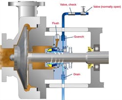
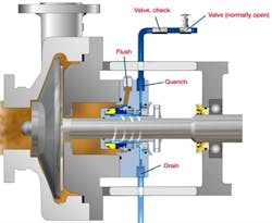
Figure 1. This approach consumes a lot of water, which flows through the seal and directly discharges into drain.
Choosing the wrong plan can undermine a processor’s efforts to maintain a high level of hygiene. The conventional seal support system frequently harbors dirt and bacteria on the interior of its main vessel; the inherently enclosed design hampers inspection, cleaning and maintaining high levels of hygiene. Therefore, for all hygiene-sensitive operations, a processor should select an alternative system designed to ease proper and effective cleaning procedures.
Common Choices
In many applications, following an API plan is an efficient and effective method of ensuring optimal operating conditions for the seal. One of the simplest forms of seal support system, API Plan 62, runs water through the seal and discharges it directly to a drain (Figure 1). This plan can provide a more hygienic method of maintaining the mechanical seal and often is found in processes that require a higher level of cleanliness. However, it is inherently expensive to operate due to the continuous high volume of water required (as much as 700,000 U.S. gal or 2.6 million L per year), potentially resulting in a lower mean-time-between-failure (MTBF) rate. Obviously, this has significant implications both on the running costs of the process and environmental concerns about water wastage.
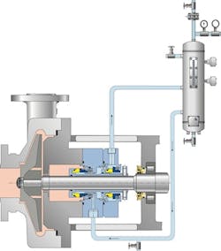
Figure 2. By using recirculation, this approach can cut water consumption by more than 99%.
An alternative solution is API Plan 53a (Figure 2). This layout utilizes a vessel to provide the seal with a constantly recirculated flow of a fixed volume of water. It can operate using a thermosyphon effect, whereby convection causes hot fluid to rise up out of the seal and draws in cooler fluid.
API Plan 53a can reduce water usage by more than 99% compared to an API plan 62 design, and has been shown to improve the MTBF of mechanical seals. When used to replace an API Plan 62 system, API Plan 53a can provide a return on investment of less than 6 months.
However, the design of current vessels makes them almost impossible to inspect or effectively clean their internal cavities. In most instances of contamination, operators aren’t aware there’s a problem (or even the possibility of a problem) until it is too late and, as a result, the consequences can be expensive and far-reaching.
Such closed systems typically have a number of cavities or “bug traps” inherent within the design, especially within the vessel. These can’t drain under natural conditions and aren’t specifically included in any cleaning regimes. Over time, these bug traps can cause issues and lead to bacterial growth and contamination. Plus, in the event of a seal failure, contaminated barrier fluid then can find its way into the process.
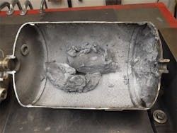
Figure 3 shows the inside of a seal support system and the extent of product accumulation — in this case, automotive paint — that can occur. Here, a world-leading carmaker was alarmed to find just how much automotive paint was migrating across the seal faces and into the seal support system. With the final finish being of paramount importance and with no way to clean the current seal support system, it turned to a two-part seal support vessel.
Better Option
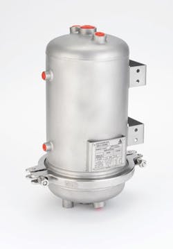
A two-part vessel is part of the latest development in water and oil API plan 53a barrier-fluid-management systems, and is aimed at environments that require a higher level of cleanliness. Its design allows the lower section to be quickly and easily opened, enabling inspection and cleaning, if needed, of the internal cavity (Figure 4). It has been shown that a two-part vessel design in an API Plan 53a arrangement, coupled with a scheduled inspection and cleaning program, can prevent contamination from the process and bacterial growth.
Figure 3. A substantial amount of paint had migrated across the seal faces and into the seal support system.
Such a design drastically reduces the chances of dirt and bacteria build-up within the internal cavity while maintaining all the water- and cost-saving features of a standard system.
This option helps avoid product contamination, reducing the chance of product rejection or even recall. In addition, a two-part vessel can be manufactured to minimize the possibility of bug traps by using filler welds, a custom-designed gasket and a sediment pipe to ensure particulates aren’t introduced into the thermosyphon stream.
Figure 4. Removable bottom section enables quick inspection for contamination and facilitates any needed cleaning.
The seal feed line usually is positioned at the lowest point of the vessel. However, it is far more effective to introduce the sediment pipe feed higher up the vessel, which greatly reduces the risk of particulates re-entering the barrier fluid line and, ultimately, the product.
Other features also can help maintain a high level of cleanliness. For instance, a clean-in-place (CIP) attachment can ensure the internal surfaces of the vessel are clean and free from unwanted deposits. This is a special fitting that screws into the top of the two-part vessel and includes a CIP ball. In cleaning operations, the appropriate fluid is pumped through the attachment and the ball gives 360° coverage, at pressure, around the internal surfaces of the vessel.
Through correct implementation of a two-part vessel as part of API Plan 53a, a processor can reduce the potential for product contamination and increase reliability while achieving greater efficiency and cost savings.
Make A Clean Break
Chemical manufacturers are doing much to establish world-class production practices and create safe, clean and environmentally conscious processes. One of the best defences against contamination, in cases where sterilization at the end of the process isn’t an option, is a robust seal-and-support-system design that insulates the process from sources of contamination. Moving to a two-part vessel design as part of an API Plan 53a on a mechanical seal system offers important benefits. In addition to minimizing the risk of contamination and bacterial growth, it can cut the amount of water used by over 99% compared to, for example, API Plan 62.
OLIVER POGMORE is innovation team leader at the AESSEAL Global Technology Centre, Rotherham, U.K. Email him at [email protected].
