Correctly Control Compressor Capacity
A new compressor station failed to operate as desired. The major problem was the feed gas contained much more condensable material than originally expected. However, other reliability problems also created operating challenges.
The station had three parallel trains of multistage reciprocating compressors. All the trains took feed from a common supply header and their high-pressure discharges entered a common product header. The product went to a pipeline.
Reciprocating compressor capacity control can include a combination of elements. The basic ones are:
• recycle;
• valve unloaders;
• pocket unloaders;
• speed control; and
• suction throttling (rarely done).
Recycle recirculates gas around the machine to reduce the net gas flow. This decreases net capacity but actual flow through the compressor and required power remain unchanged.
Valve unloaders prevent the isolation of the compressor from the feed during the compression stroke. They lower both capacity and power requirements.
Pocket unloaders mechanically add effective clearance volume to the compressor. This cuts the volumetric efficiency of the machine as well as both capacity and power requirements.
Speed control varies the compressor capacity and power by changing the stroke speed of the machine.
Suction throttling reduces the suction pressure. It decreases the volumetric efficiency of the compressor and lowers both capacity and power. Suction throttling may be a reasonable capacity control method for normal operation in some units.
Note that we haven’t mentioned discharge throttling as an option. It increases the discharge pressure and is common on centrifugal compressors. However, it’s ineffective on reciprocating compressors and never should be used. Reciprocating compressors are positive displacement machines; changes to the discharge pressure produce minimal changes in flow while using more power. Furthermore, using discharge throttling creates safety problems because of the possibility of over-pressuring the compressor from an instrumentation system fault. Such over-pressure can result in catastrophic failure of the machine and piping.
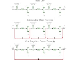
The plant operator was extremely sensitive to capital expenditure. Usually, recycle lines require the least investment for capacity control. So, a single recycle line, as shown in the bottom of Figure 1, was proposed. In normal operation, the recycle line controls compressor capacity by sending a stream from the third stage discharge to the first stage suction.
Internal reviewers at the operating company objected to this proposal. Their concern was that as feed composition changes, the amount of liquid condensed between the stages varies. Therefore, the single recycle line couldn’t effectively control the interstage conditions inside the machine. This is true.
Ideal reciprocating compressor capacity, Q, can be summarized by
where Psuction is suction pressure, Tsuction is suction temperature, Zstd is the gas compressibility factor at standard conditions, Zsuction is the gas compressibility factor at suction conditions, Displacement is a function of the physical layout and speed of the machine, and ηvolumetric is the volumetric efficiency.
The volumetric efficiency is defined by
where vclearance is the clearance volume, which the machine layout sets, Pdischarge is the discharge pressure, and 1/N is the isentropic volume exponent, which depends upon the physical properties of the fluid.
Interstage pressures between stage 1 and 2 and between stage 2 and 3 will vary as the gas composition and load changes due to the single recycle line.
The interstage pressures vary because, as feed rate to a stage changes, either the suction pressure or the discharge pressure must alter to make the process conditions align with the physical capacity constraints imposed by the compressor construction. For this machine, as rates to a stage drop, the suction pressure to that stage declines.
The operating company engineer preferred a configuration with separate recycle lines (shown in the middle of Figure 1).
Figure 1. Both recycle configurations will work but the simpler one is far less expensive.
Nevertheless, low interstage pressures — as long as they don’t cause the machine to exceed any mechanical limits — don’t present any problems. The compressor station’s customers don’t care about the interstage pressures. They only care about the discharge pressure.
A simple review of the expected limit-case compositions, i.e., those producing maximum and minimum condensation, showed that, while the interstage pressures varied with composition, they posed no mechanical difficulty for the compressor.
The configuration with separate recycles for each stage will work. However, it involves three times as many control valves and much more pipe for each compressor. Each compressor train would require three control valves in this configuration, giving a total of nine times more control valves. The single line configuration needs only one line from the common suction line to the common discharge line. The single recycle line is much cheaper.
ANDREW SLOLEY is a Chemical Processing contributing editor. You can email him at [email protected]. SCOTT SCHROEDER is a senior consultant at Advisian. You can email him at [email protected].


