Don’t Slip Up With Slipstream Filtration
Contaminated hot oil had so undermined the performance of a vaporizer that it no longer could provide the required duty. The contamination, which had occurred over time, had led to fouling of the heat exchanger and fired heater. Adding a filter for the hot oil clearly was necessary. Configuring the filtration system brought up an interesting question, one worth exploring here.
[pullquote]
Best practice for most hot oil systems is to use a partial flow filter to keep the hot oil clean. The filter treats a slipstream of hot oil. This reduces the filter size (and cost) while keeping the oil clean enough for reliable performance.
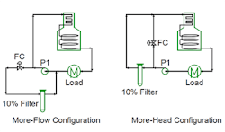
Figure 1 shows a simple hot oil system with two possible slipstream systems: a more-flow (MF) configuration (left) and a more-head (MH) configuration (right). Figure 1 focuses on the slipstream. The main circulating flow to supply oil to the thermal load has its own independent flow control system (not shown).
For the MF configuration, the slipstream goes from the pump discharge to the pump suction. As long as the circulating loop has a higher pressure drop than the filter, the only effect on the pump is a required higher flow rate. The discharge pressure of the pump can remain the same. In this system, the pressure drop in the main circulating loop sets the maximum available pressure drop for the filter. The hydraulics of the main loop potentially limit filter sizing and life.

Figure 1. The same size slipstream doesn’t mean the same size power demand.
For the MH configuration, the slipstream splits from the pump suction, goes through the filter and then returns to the main flow. The pump capacity needed doesn’t change but the pump discharge pressure must increase by the pressure drop through the filter.
Which system is better? To answer this, we focus on the pump power, P. The hydraulic power required is linearly proportional to both the mass flow through the pump, M, and the pressure rise over the pump, ∆Pr: P α M ∆Pr.
For a new unit where you have full ability to select an ideal pump, the analysis is straightforward.
To add detail to the example, let’s propose a reasonable pressure drop of 12 psi across the filter element to control filter operating costs and a pressure drop of 80 psi across the main loop in the hot oil system. The slipstream rate is 10% of the total flow required to deliver the heat load.
Using the MF system, the pump discharge pressure stays the same and the flow rate rises by 10%. The pump power goes up by 10%.
With the MH system, the total pressure drop increases to 92 psi from 80 psi. This is a 15% boost in discharge head. The pump flow rate stays the same but the pump power rises by 15%.
Most hot oil systems follow this pattern. The percent change in pressure drop required for a reasonable filter element life will exceed the percent change in flow. This is because most hot oil systems have relatively low slipstream rates and filter applications generally need relatively high pressure drops.
As the slipstream fraction goes up, the advantage shifts from the MF to the MH option in new systems. To go back to the example, shifting to a 30% slip stream rate increases the power demand of MF to +30% while MH’s remains +15%.
For adding a slipstream filter to an existing system, the choice depends upon the overall system hydraulics and configuration. In some systems, neither option will fit within existing equipment constraints.
Two other options, suitable particularly for larger systems and existing systems with constraints, are booster pumps and two-stage pumps.
If the system is large enough, a booster pump for the slipstream going to the filter may make sense. It minimizes energy consumption but incurs extra capital expense for the additional equipment and controls. Existing systems with significant hydraulic constraints may require a booster pump.
Some applications can benefit from installing a pump that discharges flow at multiple pressure levels. One example uses an API pump with a modified shaft and back head and a drilled-hole impeller second stage for the slipstream flow. In many ways, this is the ideal choice because it doesn’t require extra flow and only the flow going through the filter is at a higher discharge pressure. However, industry is far less familiar with this option; so, it has seen very limited adoption despite its benefits.
You should carefully check the hydraulics of systems with slipstream filters before arbitrarily selecting a flow configuration. The best choice will vary with system hydraulics and the size of the slipstream.
