Pre-empt Liquid Pooling In Vapor Lines

[pullquote] Low flow rates prompted by the pandemic can cause a variety of problems. Last month, we looked at the risk of sedimentation from liquid streams and the potential for under-deposit corrosion (“Keep Under-Deposit Corrosion Under Control”). Liquid pooling caused by low flow of vapor also can make corrosion worse. Knowledge gained by the pipeline industry can help us identify possible corrosion problems related to such low flow.
First, understand that vapor flows may include small amounts of liquid. For example, while a line coming from a hot separator drum, contactor or distillation tower initially only will contain dew-point vapor, minor heat losses can cause small amounts of liquid to form. If the system is mixed oil-water, the liquid could be oil, water or both.
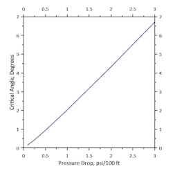
Figure 1. Line defines the maximum conditions tolerable to avoid liquid accumulation.
A small amount of water inside the pipe often is worse than a lot because it can selectively absorb ionic species from the gas. This may concentrate impurities. In contrast, extra water may dilute the mixture and lower the impurity concentration. Similar problems can happen with organic liquids. Organics may selectively absorb additives or impurities from the gas.
Many vapor-phase corrosion control additives can selectively absorb. This can prompt multiple problems. First, it robs the vapor phase of corrosion inhibitor, altering additive performance. Second, too high a concentration of inhibitor in the liquid can create deposits or other difficulties — potentially causing corrosion instead of preventing it.
Sloping lines can prevent drip accumulation and aging of liquid (see: “Grasp Line Layout”). Unfortunately, sloped lines can make piping layouts significantly more complex and expensive. Drain points are one response to this.
However, liquid can accumulate in other areas such as low points caused by damage, foundation shifting, pipe support restraints, thermal expansion or complicated pipe layouts. Pipeline corrosion work has identified liquid accumulations in sagging low points as the culprit behind many problems.
High vapor velocities keep liquid moving along and prevent accumulations. But what vapor velocity is high enough?
Basic analysis in multiphase flows with free surfaces often uses a form of the Froude number (F) — based on the ratio of the flow inertia to gravitational forces — to examine slip between the phases:
F = (ρL - ρG)/ρG × (gc × did)/VG 2 × sin (θ) (1)
where ρ is density, gc is the gravitational constant, did is the inside diameter of the pipe, VG is gas velocity and θ is the critical angle. At slopes steeper than this angle, a liquid pool forms on the bottom of the pipe. At slopes lower than this angle, momentum imparted by the vapor keeps the liquid moving.
A modified form of this equation proposed by the National Association of Corrosion Engineers for 4-in. to 48-in. pipe diameters defines the critical angle as:
θ = arcsin [.675 × ρG/(ρL - ρG) × VG 2/(gc × did)]1.091 (2)
You can use any consistent set of units, so long as they cancel each other out; the arcsin is dimensionless.
One example of the use of this equation was for investigating corrosion problems in a vapor line from an amine regenerator. The regenerator overhead acid-gas was mostly hydrogen sulfide with some ammonia and saturated with water. The question was how low a velocity the line could handle without accumulating liquid in some small pockets caused by improperly installed pipe supports.
For ease of monitoring, results were graphed as pressure drop versus the angle in the line that could be tolerated before forming a stagnant liquid spot. Because the vapor and liquid densities were relatively constant, pressure drop correlates very well with the critical angle, as shown in Figure 1.
One interesting observation from this ties directly to standard design practices for plants. For this service, designers often use pressure drops of around 1 psi per 100 equivalent ft of pipe for selecting line sizes. For a 20-ft span between piping supports, this gives a 4.25-in. deflection before liquid pools form (if the line is evenly bent). In comparison, dropping to 35% of the flow rate incurs a pressure drop of 0.125 psi/100 ft. — giving a 0.44-in. smooth deflection before liquid pooling is likely. For this plant and this line, flow rates below 35% did create the possibility of liquid pooling.
Analysis of expected flow rates identified locations needing extra care for monitoring and draining liquid low points.
The lower rates at which many plants now are operating may result in liquid pooling in lines and, depending upon system chemistry, the possibility of corrosion problems. While not perfect, using an analysis developed by the pipeline industry can help identify areas where pooling can occur.
