Solve Process Problems By Simple Mixing Analysis

Mixing often provides the critical process step that converts raw materials into useful products. Mixing and mixing equipment sometimes serve a specific purpose in processes. However, in a general sense, liquid mixing combines different materials and creates or maintains uniformity of composition, temperature, physical properties, chemical reactions or even dispersions. Nonetheless, even greater differences may exist in the processes and, indeed, not all processes improve with better mixing. Yet, the fundamental purpose of liquid mixing, to create greater uniformity through fluid motion, has some fundamental properties.
This article will focus on some of the most common and basic mixing characteristics.
The equipment. Regardless of the process, the most common requirement is to suitably adapt existing mixing equipment and tanks. Rarely do process or development engineers get to start with a clean sheet of paper to select or design new mixing equipment. Equipment limitations are most obvious when the mixing setup is more than 25 years old or relies on a mixer that was purchased used. In either of these cases and many other situations, the equipment isn’t designed for the current, modified or new process.
The process. Requirements change. Perhaps you need to improve an existing process, adapt a process to make new but similar products, or set up a totally new process somewhat akin to an existing one. Regardless, you need good mixing. You always want to avoid a mixing failure in a stirred tank.
If the current process or equipment fails to provide the production needs, something must change. Either the process or equipment may require modification. The first step is to get a good idea of the current mixing conditions and capabilities.
Calculating a mixing index (MI) can give an indication in relative terms. Here, we’ll focus on MI calculations for vertically mounted, impeller-type mixing equipment in cylindrical tanks, as represented in Figure 1. To avoid confusion and complicated correlations, the basic equations presented here apply to turbulent mixing conditions. We’ll provide definitions and discuss exceptions and alternative conditions as we progress.
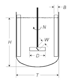
Figure 1. Calculations use conventional units, e.g., inches, revolutions/minute and gallons.
We’ll use customary units for the terms given in the figure — inches for length dimensions like the impeller diameter, D, and tank diameter, T; revolutions per minute for the rotational speed, N; and gallons for the volume, V. Because we’re focusing on turbulent conditions, we’ll need vertical wall baffles to control rotational flow with on-center, vertical mixers. Without such baffles, a deep surface vortex usually will result; it provides almost no vertical or radial mixing. Properly positioned offset, angle-mounted portable mixers can create effective mixing patterns without baffles but the following calculations only may approximate their performance.
The MI calculation provides a value between one and ten that gives an indication of mixing intensity. A MI less than one means mixing intensity likely won’t enable sufficient fluid motion to keep the entire tank contents in motion. A MI of ten represents a mixing intensity at or above typical conditions for practical industrial applications. The one-to-ten scale offers an approximate but useful description of complicated mixing flow patterns and local velocities.
Essential Element
While mixing results in many situations depend on particular processing characteristics, fluid motion is essential to all of them. Process results, such as blend time, solids suspension, gas or liquid dispersion and heat or mass transfer, may require more-specific conditions to achieve desired results. The MI concept takes the basic fluid-pumping characteristics of a mixing impeller and converts the discharge flow into recirculating motion throughout the stirred tank. While the origin of the MI calculations [1] can be described on the basis of hypothetical assumptions about circulation flow in a stirred tank, the actual purpose of those explanations is to achieve a practical quantification of mixing intensity. In this case, the result is more important than the background explanation.
However, many independent and related studies that have generalized experimental results [2] support the explanation and practical values. Mixing technology is based on empirical results, which means that experimentation, not just calculation, is needed to create and justify the correlations. In many academic and even industrial studies, the details of the experimental methods or measurement equipment affect the exact results. In the industrial world, process variability may make such prescribed conditions difficult or impossible to achieve. The MI is a practical way of generalizing mixing intensity for different industrial processes and mixing impellers.
The definition and calculation of the MI take advantage of the general relationships between impeller power number, pumping number and other experimental measures of mixing performance. Most typical measures of mixer operation have limits or involve different evaluations in different situations. For instance, the power requirements of mixer operation must be matched to motor power capabilities. All impeller power inputs are 100% efficient. The power input by a mixer eventually degenerates into molecular motion, which is heat. However, not all power is effective in accomplishing the fluid motion and process requirements. Obviously, power per volume is a better measure of mixing capability than just power because the same amount of power applied to a tank of liquid will have less process impact in a larger tank. Other measures of process effect, such as blend time or turnover time, can be difficult to use as process objectives. Assumptions of longer times aren’t conservative. Longer times mean that less mixing intensity is required; less mixing usually will produce poorer process results.
Another problem with other common measures of mixing, such as differences between flow and shear, is that the type of impeller being considered can affect success. Axial-flow and radial-flow impellers create different flow patterns. Some types of axial-flow impellers can yield better process results in similar applications. To accommodate the effects of different impellers, much of the behavior is reflected in different turbulent power numbers. Power numbers primarily are functions of the impeller geometry and pumping results. In the case of axial-flow impellers, the power number also relates to the pumping number, much like the relationship between lift and drag coefficients on an aircraft wing or propeller blade.
By focusing this basic discussion of the MI on turbulent mixing, the turbulent impeller power numbers effectively are constant values for mixers operating in baffled tanks. The pumping numbers for similar conditions also are constant for turbulent conditions. We can overcome the limitations imposed by the assumption of turbulent mixing by the use of viscosity correction factors, which are part of a longer, more complicated article for another day.
Calculating MI
Turbulent conditions for mixing exist not only because of low viscosity but also in combination with impeller size and rotational speed. The typical definition of turbulent mixing conditions is based on the impeller Reynolds number, NRe, exceeding 20,000. The Reynolds number is a dimensionless variable that represents a ratio of inertial forces to viscous forces. Turbulence occurs when inertial forces dominate over viscous forces.
NRe is defined and evaluated by:
NRe = (10.7D2×N×ρ)/μ (1)
where D is impeller diameter, N is rotational speed, ρ is the fluid density and μ is the fluid viscosity.
You can calculate the MI for turbulent mixing conditions by the following expression:
MI = 4.05×10⁻⁴(Np⅓ND5⁄2)/V½ (2)
This combines the effects of a turbulent power number, Np, rotational speed, N, impeller diameter, D, and liquid volume, V. Each variable accounts for the essential factors that affect mixing intensity. Np reflects the impeller geometry as it influences the ability and efficiency of the design to pump liquid. N and D describe the impeller operation. V puts the mixer capabilities in perspective relative to the batch size.
The inclusion of Np links different impeller types to the same evaluation criterion. A pitched-blade turbine giving a MI of 3.0 should provide the same mixing intensity as a hydrofoil impeller with a MI of 3.0. Typically, Np is 1.37 for pitched-blade turbines, 0.30 for hydrofoil impellers, and 3.96 for straight-blade (non-disk) radial-flow turbines. You can use corrected or alternative power numbers for impellers with different numbers of blades, blade angles, blade widths and other dimensions. However, extreme refinement of any factors in the MI calculation isn’t practical or important because the MI is no more precise than two significant figures or one decimal place. You might observe a change between a MI of 3.0 and 4.0 in an industrial application but probably won’t detect any difference between a 3.2 and 3.3.
The following example will demonstrate a MI calculation for a hypothetical tank. Assume the tank is 72 in. in diameter with an 80-in. straight side and an ASME head on the bottom. The process involves mixing 1,400 gallons of a 10-cP liquid with a 1.2 specific gravity. The mixer in the tank has a 26-in.-dia. pitched-blade turbine turning at 68 rpm.
The first thing we should do is calculate NRe to check the process is turbulent before we use the turbulent MI calculation.
NRe = (10.7D2×N×ρ)/μ = [10.7 (26)2×68×1.2]/10 = 59,023 (3)
NRe exceeds 20,000, so our example is turbulent.
The next step is to put these same mixing values into the MI calculation.
MI = 4.05×10⁻⁴(Np⅓ND5⁄2)/V ½
= 4.05×10⁻⁴[(1.37)⅓(68)(26)5⁄2](1,400)½ (4)
The MI for our example is 2.8, which represents a moderate mixing intensity on the 1–10 scale.
Other Consideration
While the calculation of a MI provides a way to evaluate a mixer in a particular application, not all process improvements depend on just estimating a mixing intensity. Sometimes, even with existing equipment, predicting how changes might alter or improve the MI is important. For instance, suppose you’re considering a different impeller type. Switching from a pitched-blade turbine to a hydrofoil impeller may provide more pumping, resulting in greater mixing intensity. However, merely replacing the current pitched-blade turbine with the same size hydrofoil impeller will decrease the MI because of the lower power input by the hydrofoil impeller. The lower power input also will reduce the pumping ability of the hydrofoil for the same diameter impeller.
To do a practical MI calculation for changing from a pitched-blade turbine to a hydrofoil impeller, we must start with an equal power hydrofoil impeller. We must use a hydrofoil impeller with a larger diameter than the pitched-blade turbine to input the same power at the same speed in the same liquid. Because the other factors in the power calculation, ρ and N, remain the same, we can calculate the hydrofoil diameter by rearranging the turbulent power for the different impeller types:
NpHydrofoil(DHydrofoil)5 = NpPitched-Blade (DPitched-Blade)5 (5a)
DHydrofoil = (NpPitched-Blade/NpHydrofoil)⅕(DPitched Blade) (5b)
Using the conditions from our example MI calculation, we get:
DHydrofoil = (NpPitched-Blade/NpHydrofoil)⅕(DPitched-Blade)
= (1.37/0.30) ⅕(26.0) = 35.2 (6)
If we now go back to our MI calculation for the equivalent power hydrofoil impeller, i.e., a 35-in.-dia. one, we find the following:
MI = 4.05×10⁻⁴(Np⅓ND5⁄2)/V½
= 4.05×10⁻⁴[(0.30)⅓(68)(35)5/2]/(1,400) ½ = 3.6 (7)
This calculation tells us we could expect to see the MI increase from 2.8 with the pitched-blade turbine to 3.6 with the hydrofoil impeller on the same mixer drive. We should see the effect of the higher MI for liquid blending applications; it also may improve other processes, such as solids suspension. Of course, use of a larger and probably heavier impeller necessitates a check of the mechanical design.
You can rearrange the MI calculation to do some other mixer design calculations such as solving for N at a desired MI, V, Np and D. A different rearrangement of the MI equation also can calculate D for a given MI, V, Np and N.
To account for the effect of viscosity in the MI calculation, you must include an empirical correlation for reduced impeller pumping at lower NRe in the calculation. You can approximate the effective MI for multiple impellers by doing separate calculations for each impeller using the total batch volume. The square root of the sum of squares of each separate impeller MI will give a reasonable value for the total MI.
Of course, the MI calculation is a simplification of complicated flow patterns in a stirred tank. If the impellers are typical of those used on vertical, top-entering mixers and are at effective locations in the tank, the MI calculations will provide reasonable estimates of mixing intensity. Don’t count on the calculations for accurate direct comparisons of vertical mixers with other geometries, such as off-center, angle-mounted portable mixers. However, comparisons among portable mixers may give reasonable results.
The MI doesn’t directly represent other mixing applications, such as solids suspension. However, other applications do need a MI value exceeding 1.0 to expect full liquid motion and may not be practical for MI values greater than 10.0.
DAVID S. DICKEY is a senior consultant at MixTech, Inc., Coppell, Texas. E-mail him at [email protected].
REFERENCES
1. Hicks, R. W., Morton, J. R., and Fenic, J. G., “How to Design Agitators for Desired Process Response,” Chem. Eng., pp. 102–110, April 26, 1976.
2. Dickey, D. S., “Liquid Mixing in Stirred Tanks,” Chem. Eng., pp. 24–35, August 2019. (Note: The coefficients in Eq. 15 in that publication are incorrect; use Eq. 2, in this article to calculate mixing intensity.)