Fluid Handling: Are You Playing Vacuum-System Roulette?
The vacuum ejector is the most common choice for evacuating process equipment and keeping it under vacuum. For cost reasons, most systems rely on steam as the motive fluid. Steam ejector systems include other components besides the ejectors; the discharge vapors, including the motive steam, go to condensers, with condensate passing to a hot well to allow recovery for treating.
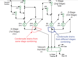
Figure 1 shows a three-stage ejector system with condensers after each stage. This type of system routinely serves to provide vacuum down to a pressure of 3 or 4 mm Hg at the suction of the first stage. The hot well takes the condensate from all three stages and collects the water for subsequent treating as well as separating any light slop oil present.
System performance depends upon the interaction of all its components, including how the ejectors, condensers and drum interact with each other. In addition, how components are connected is important. Piping layout and possible piping problems often are overlooked. However, piping layout does matter, especially in gravity-flow systems that depend upon static head.
Figure 1 includes two piping configurations that are not best practice for vacuum systems. The four condensers only have two lines to the hot well. The condensate drains from E2 and E3 combine before going to the hot well; likewise, the condensate drains from E1A and E1B join ahead of the hot well. Best practice calls for a separate line from each individual condenser to the hot well. While the combined-lines configuration adopted certainly decreased initial cost, it both reduces reliability and makes troubleshooting more difficult — as a recent troubleshooting assignment pointed up.

Figure 1. This design conflicts with best practice by combining condensate drains both for a single stage and multiple stages.
Combined lines in vacuum systems are fairly common, as a quick survey of a number of vacuum systems I’ve worked on highlights. Granted this isn’t a random survey, but it still is informative. The 81 systems reviewed included 2- to 4-stage ones with a common hot well. Of these, 12 (15%) had condensate drains from different vacuum stages joining together. Combined lines also are possible at the same vacuum stage when the stage uses more than one condenser. Of the 81 vacuum systems, 27 had multiple condensers in at least one stage, with seven of these (26%) having combined drains. To make things more complex, another four systems contained both same-stage and different-stage combined drains.
The base problem here is that all the drains flow down to the hot well by gravity. The hot well is at a higher pressure than the vacuum ejector discharge. The vertical distance from each condenser to the hot well must enable enough static head to accumulate for the condensate to flow.
For example, in the system I recently had to troubleshoot the pressure in E2 was 280 mm Hg. If the hot well is at 800 mm Hg, then the height of liquid in the condensate line from E2 to the drum must provide 520 mm Hg of static head (11.6 ft of water) as well as additional head to cover line losses. As long as each condenser has enough height above the drum and the design accounts for the possible range of densities of the condensate, separate condensate lines insulate the static head requirements of each condenser from each other.
Combining condensate drains from different pressure levels, as shown with E2 and E3, makes the situation complex. Depending upon the piping geometry and connection point, vapor might recycle from E2 to E3 or the liquid level in the E2 drain might rise. The elevations will determine if high liquid level in the E2 condensate line matters or not. Additionally, the consequences can change as E2 pressure varies. A whole range of possibilities can arise that defy simple explanation in the space here. These situations also can stymie straightforward troubleshooting.
Joining together multiple drain lines from the same stage, as shown with the two condensers in the first stage in Figure 1, presents fewer problems. While still a poor practice, at least the condensers have identical or nearly equal pressures. As long as the junction is at least a couple of feet below the parallel condensers, problems are rare. Nevertheless, they still can occur.
Most of the time, shortcuts like combining condensate lines work. Nevertheless, best practice is to use separate lines. While joining lines together can reduce initial cost, such a move increases the probability of problems. I can’t say how many of the 23 systems with combined condensate lines in my survey suffered problems for that specific reason. However, I can tell you the one unit I’m sure had problems due to it created costs that surely exceeded the savings on all 23 units. Combining lines is like playing roulette but, in this case, if your number comes up, you lose.
