Flow Meter Design: Bend It Like Coriolis
A discovery made by Gaspar Gustav de Coriolis (1792-1843) in 1835 made possible the development of the highly accurate dual curved-tube Coriolis flowmeter, and the more compact single straight-tube meter.
It was Napoleon who asked de Coriolis to explain why his cannon balls never went straight. History doesn't tell us whether he ever gave Napoleon a good explanation - that phenomenon is caused by an entirely different effect - but de Coriolis' research led to his discovery of the Coriolis effect. A century or so later, Coriolis technology spawned a whole new family of accurate meters.
First, the weather report
Most people are familiar with the Coriolis effect on weather patterns. Because of the jet streams, the clouds tend to move east and west across the planet. However, the rotation of the planet creates the Coriolis effect, which deflects clouds as they move, causing them to spin or rotate. That cloud rotation causes the planet's storms.
Applied to instrument design, Coriolis flowmeters can measure mass flow directly, as well as volume and density. In process plants, mass is a vital measurement,"the basis of all chemical reactions, mass and energy balances, and almost all process flow operations.
Before the availability of Coriolis meters, mass was measured by weighing liquids on a scale. This can be appropriate for batch process operations, but not for continuous processes. There, methods such as orifice plates and magnetic flow tubes measured only volumetric flow and required temperature and pressure corrections and calculations using additional instruments to convert readings to mass.
A volumetric flowmeter is affected by changes in the temperature, as well as by pressure, density, viscosity, and the flow profile of the process fluid. By comparison, a Coriolis flowmeter provides a direct mass measurement that is unaffected by changing process fluid characteristics.
Direct mass measurement
In a dual-tube Coriolis meter, a manifold splits the flow through each of the two tubes. The full flow always goes through the sensor. The two vibrating tubes rotate around the two fixed end points, creating a Coriolis effect when mass flows through.
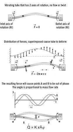
When there's no flow, fluid on both sides of the U-shaped tube is subject to the same force, so there is no twist (Figure 1). When fluid is flowing, it accelerates (changing direction) on the inlet side and decelerates on the outlet side. As a result, reactive force on the inlet side is opposed to the motion of the tube, and reactive force on the outlet side operates in the same direction as the motion of the tube. The tube is twisted ever so slightly by these opposing forces. The amount of twist is proportional to the mass flow rate.
Figure 1. Coriolis Forces in Action
In a dual-tube Coriolis meter, the two vibrating tubes rotate around the fixed end points. When fluid is flowing, reactive force on the inlet side is opposed to the motion of the tube, twisting it ever so slightly. The amount of twist is proportional to the mass flow rate.
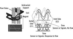
To exploit the Coriolis phenomenon, a magnet is attached to one tube and a pickoff coil is attached to the other tube at both the inlet and the outlet of both tubes (Figure 2). Because of vibration, the coil moves into the magnetic field and generates a sine wave proportional to that motion. Because the coils and magnets are referenced to each other (one element moves with each tube), the sine wave represents the relative velocity and position of the tubes. When the waves cross zero, the tubes are momentarily at rest before changing direction.
Under no-flow conditions, the two sine waves are in phase, or on top of each other. Under flow conditions as the tubes twist, these sine waves shift apart. The instrument measures the twisting, which is directly proportional to the mass flow.
Figure 2. Phase Change Finds Flow
To exploit the Coriolis phenomenon, a magnet is attached to one tube and a pickoff coil is attached to the other tube at the inlet and the outlet. Under flow conditions as the tubes twist, the generated sine waves shift apart. The instrument measures the twisting, which is directly proportional to the mass flow.
Get it straight
The same analogy applies to a single straight-tube meter. The tube is vibrated along the center of the axis. Because the tube is fixed at the ends, the vibration creates two rotating reference frames. The rotation of the inlet side is in the opposite direction of the outlet side, creating the opposing Coriolis forces.
At the inlet side, the tube is rotating in one direction, say upward, but the fluid is restrained by the wall and the substrate and now it is vibrating up, creating a force downward. When the fluid passes the centerline lengthwise and is rotating in the opposite direction, the tube wall restricts the rotation, which creates a force in the opposite direction.
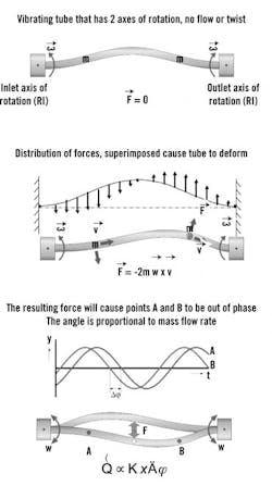
Figure 3 shows an exaggeration of the deflected shape. Here again, there are two forces proportional to the mass flow rate. The Coriolis effect is generated, as it is in the double curved tube, through the rotation of the tube about fixed ends. The two sine waves on the inlet and the outlet are shown as Point A and Point B in Figure 3. The inlet side lags the outlet side, which is identical for either straight or curved tubes.
Figure 3. Single-tube, same technology
The Coriolis effect is generated, as it is in the double curved tube, through the rotation of the tube about fixed ends. The two sine waves on the inlet and the outlet are shown as Point A and Point B. The inlet side lags the outlet side, which is identical for either straight or curved tubes.
Software allows designers of single straight-tube meters to ensure the response of the Coriolis signal is not affected by changes in the density or mounting options. The sensor element, which is relatively immune to environmental changes, takes into account that the Coriolis forces are changing with fluid density at the appropriate vibration levels.
Each design has merit
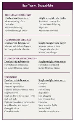
There are similarities between dual, curved-tube and single, straight-tube meters, but also some significant differences. The key differences are how they behave to mounting effects, fluid density changes, and temperature changes.
The dual curved-tube meter is much more immune to meter-mounting variations. The two tubes are essentially identical. When they vibrate in opposition to each other, they are extremely well-balanced. All the energy is contained within these two tube sets, and nothing is transmitted out to the environment. The tubes are "unaware" of the environment, because everything is maintained within the sensing elements themselves.
The same attributes make the dual curved-tube meter reliable despite fluid density changes. Because these two tubes are identical, when the fluid density changes within them, they respond identically.
These tubes extend from the pipeline and are relatively free to expand. Therefore, as the temperature changes, they grow in length, unrestrained, with no stresses or loads generated through expansion. A single measurement compensates for the effect of temperature on the modulus of the material.
In contrast, single straight-tube meter mounting presents challenges. The single-tube system was designed to be symmetric from inlet to outlet, but during vibration, the flow tube and reference tube don't vibrate to the same extent, so the single-tube meter is not inherently balanced. The reference part was designed to maintain that balance, but it responds to vibration as if no vibration leaked out the ends.
As fluid density changes, it only changes in a single tube, not in the reference tube. A great deal of research was invested to understand the dynamics and make these meters stable as fluid density changes. The design of the reference tube is vital for stable vibrations throughout the entire density range.
The most challenging design aspect of single straight-tube meters is dealing with temperature changes. Its case is fairly rigid, so it holds pipeline loads. It also holds the tube very rigidly. A fluid temperature change will change the tube, but the case will not allow it to expand.
Best use
The differences between curved tubes and straight tubes will impact user applications. Every plant or facility has a variety of needs for applications and measurement points, which often require significantly different specifications. One example would be a material balance, in which many different streams are combined. The output should be very consistent, but the error tends to increase as more streams are added together. In this case, users will want very high accuracy, because the errors will multiply throughout the measurement points.
To solve this problem, the user could choose a dual curved-tube meter because of its ability to deliver highly accurate and repeatable measurements. When blending or combining different materials, if operators are changing the amounts of materials that they are combining, they might add them at different flow rates. The dual curved-tube meter's increased accuracy also gives it a higher rangeability, from 100 percent of flow to 2 or 3 percent of flow, with very little degradation of the measurement.
In some cases, when operators are just blending and filling, a mass measurement is required but it doesn't need to have the same accuracy as in the material balance situation.
Despite the dual meter's superiority, some users will want to select the single straight-tube meter. If a volumetric meter is being replaced, there might be a limited amount of space to install a new meter between closely spaced pipe flanges. The compactness of the straight tube might make it preferable. The straight tube is also easy to make highly sanitary.
Chuck Stack is director of sensor technology for Micro Motion, Boulder, Colorado.


