The stirred batch reactor is a workhorse at many fine and specialty chemical plants, frequently serving multiple purposes. It can handle not just reaction but solvent extraction, crystallization and distillation. The successful installation of such a reactor depends to a great degree upon the proper design of its temperature-control system.
The most critical factor is the design operating temperature range. This, coupled with a site’s practices and the initial fill cost, drives the selection of a heat transfer fluid (HTF).
An HTF must not be used at temperatures above the manufacturer’s recommended maximum. It is considered good practice to select a fluid with temperature capabilities at least 20°C (36°F) higher than the required process maximum to safeguard against fluid breakdown. Table 1 summarizes the temperature capability of some common HTFs.
Note that the food industry prefers propylene glycol, due to its low oral toxicity, to ethylene glycol. Glycol water-based systems require inhibitors to keep dissolved oxygen from forming organic acids, which can cause corrosion and fouling.
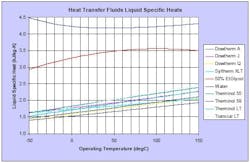
Wherever possible, avoid pressurized systems by selecting a fluid with acceptable vapor pressure at the maximum operating temperature. This will simplify system design and operation. Then, evaluate the suitability of other crucial physical properties over the operating temperature range. The specific heat of water-based and organic HTFs can vary significantly. As Figure 1 shows, water has a higher heat-removal capability.
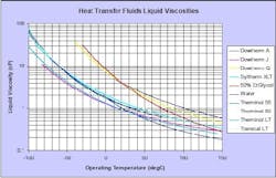
The liquid viscosity throughout the operating temperature range is a key parameter. At low temperatures, viscosity effects can become limiting, resulting in low jacket/coil-side heat-transfer coefficients and high pressure drops (Figure 2). Selection of an HTF with reasonable viscosity characteristics and an acceptable freeze point will allow operations down to -90°C (-130°F) [1].
Fluid tradeoffs
Organic HTFs offer a number of advantages:
• liquid state throughout the operating temperature range, which simplifies the control system, equipment configuration and operation;
• stable fluid properties over a wide temperature range;
• less corrosion and erosion of heat-transfer surfaces than water;
• controllable temperature differences, which minimize thermal shock effects; and
• flexibility to handle a variety of services.
However, they also pose disadvantages:
• lower thermal efficiency than water-based systems;
• higher initial equipment and installation costs;
• significantly greater cost for initial fluid charge;
• propensity to leak;
• special commissioning, operational and maintenance procedures;
• longer downtime on equipment failure; and
• flammability, toxicity, odor and good manufacturing practice (GMP) concerns.
These HTFs will aggressively search for any leak paths and this must be considered when selecting equipment and specifying piping. Use sealless pumps for fluid circulation. To achieve the flow required to prevent bearing damage, install a restriction orifice in a spillback line. The piping design should specify ANSI 300 flanges, as a minimum, to allow for high bolting torques. The gaskets should consist of an asbestos-free filler reinforced with a stainless steel spiral.
These systems have to be thoroughly dried out by heating during commissioning to prevent operational problems and equipment damage. This can take days on large installations and needs to be done slowly to avoid equipment damage due to steam hammering. Manufacturers do not recommend water for pressure testing, preferring a suitable dry alternative. However, this is not usually feasible during the construction phase.
Water breakthrough, due to contamination or equipment failure, can result in considerable downtime to identify and rectify the problem. At low temperatures, water breakthrough will result in freezing, leading to loss of circulation and possible equipment damage.
Reactor parameters
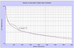
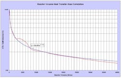
The heat-transfer-area/reactor-volume ratio increases as the reactor size decreases (Figure 3). This needs to be considered carefully during scaleup and underscores the importance of correctly matching reactor size to batch size. Partially filled reactors not only reduce the heat-transfer area but can cause mixing problems and exothermic reaction instability.
The thermal conductivity of materials of construction significantly impacts reactor wall temperatures and, thus, can limit cycle times. Extreme temperature differences can result in product quality problems on certain processes. (The density and specific heat differences among materials aren’t a critical factor in heat transfer.)
As vessel size increases, so too does the cross-sectional area for fluid flow, which is determined by the annulus width for jackets and the pipe diameter for coils. Unbaffled jackets result in laminar flow, which gives poor thermal performance. Baffling in the jacket annulus, dimple jackets, half coils and inlet agitating nozzles can provide higher velocity. Mechanical design, construction and cost constraints can limit options [2, 3].
Stirred batch reactors, with coils or external jackets, have inherent thermal lags due to the heat capacities of the masses associated with the reactor, reaction mix, jacket contents and jacket services [4]. To minimize these lags, reduce, wherever possible, jacket service volumes and thermal masses associated with external equipment and also install good thermal insulation.
A study of the heatup and cooldown curves or responses to setpoint step changes can provide an estimate of time constant. For instance, the typical overall value for heating 1,000 kg of toluene in a 1,600-L Hastelloy C reactor with Dowtherm J fluid is 21.1 minutes; breaking down this estimate into the contributions for the different interfaces gives the inside contributing 15.4 minutes, the wall 3.1 minutes and the outside 2.6 minutes.
Endothermic reactions exhibit a marked degree of self-regulation in regard to thermal stability and do not need further consideration.
Exothermic reactions, however, require a detailed understanding of kinetics to obtain rate and heat of reaction. The heat removal capability is a function of the resistances to heat transfer, the temperature difference and the heat-transfer area. Reaction temperature increases lead to a higher rate of reaction and pose a risk of thermal runaway if heat cannot be removed fast enough; any reduction in heat-transfer area due to a decrease in reactor contents adds to the problem. Design cannot always provide stability where not enough heat-transfer area is available for the temperature difference. However, removing heat by boiling one or more of the components can ensure stability because this tends to create an isothermal system.
When reactions are carried out with all the reactants charged, carefully consider the implications of cooling failure, taking into account common mode failures. It is preferable to limit the reaction rate by adding the reactant continuously at a controlled rate to ensure that the heat generated does not exceed the system’s heat-removal capability.
Tempered reactions, i.e., those operating at the boiling point, remove heat using the latent heat of vaporization. This procedure is self-regulating, provided the sizing of the overhead condenser ensures material is not removed from the reaction (which would decrease the heat-transfer area). In this case, the reactor cooling system only needs to remove any excess heat from the reaction.
Gassy systems generate a permanent gas and require the total heat evolved to be absorbed by the jacket/coil cooling system.
It has been empirically established that a velocity of 1 m/s across the service-side heat-transfer surface will provide optimal economic heat transfer. Achieving this necessitates the use of circulating pumps and jacket-inlet circulating nozzles, which induce a rotational movement similar to spiral baffles and significantly reduce the circulation flow required for efficient heat transfer. The combined reactor and nozzle pressure drop determines the number and size of mixing nozzles. Vendors provide curves to establish the optimal circulation rate and pressure drop [5].
When using HTFs that might have high viscosities within the operating temperature range, circulating nozzle pressure drops might become limiting and half pipe coil constructions might be required.
Minimize the heat load on the refrigeration system by first using a higher-temperature cooling service and then switching to a lower temperature medium only when necessary. Excessive evaporator temperature in the refrigeration loop can result in compressor shutdown and, ultimately, failure. Any water present in the system will accumulate and freeze at the compressor suction.
Boilup and wall temperature might be excessive with direct steam and might require pressure control. Boilup can be limiting with indirect HTF systems and only can be boosted by raising the jacket temperature, which is subject to maximum operating-temperature constraints.
External heat exchangers
Batch operation can involve rapid temperature cycling that leads to severe thermal stresses. Therefore, use a fully welded shell-and-plate heat exchanger rather than a less expensive brazed unit, which might experience stress failure. The thermal fluid is usually on the plate side and the service fluid on the shell side. For cryogenic applications, opt for a coiled-tube heat exchanger with liquid nitrogen on the tube side [6].
Base the heat duty for exchanger sizing on the reactor heat-transfer area available at maximum operating level.
Inlet and outlet temperature differences are determined from the services’ supply and return temperatures and by selecting reasonable HTF inlet and exit temperatures at the approach to the services’ inlet temperatures.
For heating with steam, the inlet and outlet temperature differences are unlikely to be critical at the approach to maximum HTF temperature.
For cooling, the inlet and outlet temperature differences can be critical at the approach to minimum HTF temperature, particularly for low-temperature applications. Select a design temperature difference that gives an economic design while providing a heat-transfer capability that exceeds the reactor’s by a reasonable margin.
The liquid service flow is established by setting an acceptable temperature difference across the heat exchanger, typically 10°C (18°F). The type of cooling system and its operation determine the allowable return temperature.
A characteristic of plate heat exchangers is that the cross-sectional area for flow is small and the pressure drop, particularly at low temperatures, usually sets the number of plates and their geometric arrangement.
The heat-transfer area is estimated thermally, and the configuration then is adjusted to give an acceptable pressure drop. The plate area determined by pressure drop, usually on the circulating heat-transfer-fluid side, normally results in an increased design margin for heat-transfer area.
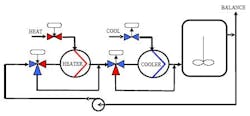
As reactor size increases, the thermal lag from reactor contents to reactor wall increases and the heat-transfer area per reactor volume decreases. Temperature control is characterized by sustained errors between setpoint and measurement during heatup and cooldown and by varying thermal responses.A typical control system has the reactor contents’ temperature primary controller output being cascaded to the jacket/coil temperature secondary controller setpoint.The primary control modes normally are proportional (P) plus integral (I) plus derivative (D), with P typically set in the range 35% to 50%, the I mode set slower than the overall time constant and the D mode set at I/4. The I mode should only be activated when the measurement is within the proportional band; it should be set conservatively, ensuring that energy is not driven into the process at a rate faster than the process can accept it, to prevent oscillation.The secondary control mode normally is a P-only controller, with P set < 25%, as the I mode slows down the response.Distillation boilup is determined by the temperature difference between jacket/coil and reactor contents. Boilup is controlled by the jacket/coil inlet temperature; the secondary controller will require I mode to be activated to eliminate offset. For high-accuracy temperature measurements, use a resistance sensor with a Smart transmitter to provide flexibility when setting ranges. The thermal lag associated with the sensor is minimal. However, there can be a significant thermal lag associated with the thermowell if it is incorrectly designed or installed, and this can lead to an uncontrollable system. Fast response designs are available and should be used.Satisfactory performance depends upon the selecting a control valve with the appropriate operating characteristics. A valve has an inherent characteristic (relationship between flow and stroke at constant ΔP) and an operational characteristic where the inherent characteristic is modified by the process pressure conditions. An equal-percentage operating characteristic tends toward a linear characteristic as ΔPmax/ΔPmin increases. A linear operating characteristic tends toward a quick opening characteristic as ΔPmax/ΔPmin increases.An equal-percentage valve characteristic normally is used for temperature control, although situations might arise where a linear characteristic provides better control. The operational characteristic of a valve can be modified by controller output-signal characterization.Use pneumatic control-valve actuators with positioners. The calibration for split-range operation of the valves should be achieved at the positioners, not with scaled multiple controller outputs, to ensure loop integrity is maintained under all failure modes.Heating/cooling configurationsThree options are available:Direct heat/direct cool. The appropriate supply and return services are connected directly to the reactor jacket/coils. Temperature ranges from -20°C to +180°C (-4°F to 356°F) with water, steam or ethylene glycol/water are possible with pressurized systems. Arrangements vary from totally manual to fully automatic and include forced circulation with steam/water mixing facilities. Combined heating/cooling facilities require automatic valve sequencing and jacket/coil blowdown routines when changing services. This configuration exhibits good thermal response. Potential operational problems include cross-contamination of services, jacket fouling, corrosion, thermal shock of glass-lined equipment and product degradation from high wall temperatures.Indirect jacket heat/direct cool. This uses a single HTF, with the coolant being injected into the reactor circulating loop. Heating is provided by a heat exchanger with steam on the service side. Changeover between heating and cooling mode is seamless using control valves in split range. However, in a multiple-reactor facility, this system does not provide complete segregation of the reactor service system from the other reactors. This could result in an extended shutdown of the total facility in the event of water breakthrough due to a single heat exchanger failure.Indirect jacket heat/indirect cool. This is probably the most common arrangement. As shown in Figure 4, a three-way valve at the steam heat exchanger provides fast-response bypass control by eliminating the thermal lag associated with the heat exchangers [4]. Steam can be applied continuously to the heat exchanger shell at full pressure, eliminating problems associated with condensate lift and return, preventing freezing when operating below 0°C (32°F) and providing excellent linear control characteristics. Thermal response on cool is slower than direct injection due to the added thermal lag of the cooling heat exchanger. This exchanger allows for a less expensive fluid for the cooling service, which might provide cost benefits over a centralized refrigeration facility involving the use of significant volumes of an HTF. In such a system, take care to allow for thermal expansion throughout the loop.
This system also allows for segregation of the reactor service system from other reactors, which enables rapid identification of water breakthrough problems at a facility with several reactors.
John Edwards is a Senior Consultant for P & I Design Ltd., Thornaby, England, where he is responsible for process modelling and engineering. E-mail him at [email protected].
