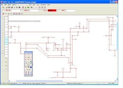
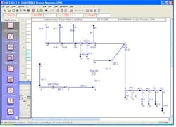
If you can’t solve the mystery of why your process is not performing to its required capacity and quality target, you may be limiting your chances by using simulation software only to analyze the system from a process flow diagram (PFD) perspective. By digging a little deeper into the piping and instrumentation diagram (P&ID) level, you may be able to quickly and definitively identify chronic flow and pressure drop problems that may have existed in your facility for years.
To illustrate the power and benefits of using pipeline simulation at the P&ID level, we will look at recent in-depth fluid flow studies of medium-sized distribution systems at Shell Chemical LP and Eastman Kodak Co. In both cases, root cause problems were conclusively confirmed and quickly corrected at minimal costs with a significant positive impact on plant profitability and safety.
The primary “unit operation” of a pipeline simulation analysis is the “pipeline,” which realizes increased pressure drop as flow rate increases. Pipeline systems typically have to be analyzed as a whole to find the one “needle in the haystack” component whose design flow or pressure drop has been exceeded or compromised in some fashion. You must include all of the “minor” components found in a P&ID such as control valves or orifice plates. These minor components can account for more than 50% of the total system pressure drop in some cases. A single such component can cause a problem that may significantly limit your plant’s profitability and seriously compromise process safety. And, as long as this deviation from normal design remains a mystery, its negative impact will endure.
How do problems in the piping, instrumentation and related components affecting flow and pressure drop even occur? Wasn’t the design done properly in the first place? The answer is “yes” for a particular design flow rate. However, at many sites, capacity has been substantially boosted in the years or even decades since the plant was first designed and installed (a fact we tend to sometimes ignore in our search for the “truth” in underperforming systems). With the majority of new facilities being built in Asia and the Far East, the U.S. chemical industry is forced to make due with the plant facilities (piping and related components included) already in place.
Most companies have done an excellent job in expanding the capacity of major equipment items to significantly improve bottom-line profitability. They have focused on unit operations and performed in-depth analyses. They have identified options by simulating various changes in operating conditions, supplementary processing, etc., using traditional process simulation tools.
However, fluid flow analysis has been minimal at many companies or even completely overlooked by them. Yet, fluid flow issues may drastically affect capacity and even safety. The good news is that pipeline simulation software is now a mature technology that can focus directly on the P&ID component level of a plant (the level you have to live with). It can zero in on the piping-related components that may be taking a toll on your plant’s profitability and safety. And, solutions typically cost only pennies on the dollar compared to common brute-force workarounds that can otherwise result when the root-cause problem is not actually found.
Now, let’s see specifically how pipeline simulation has been put to good use recently.
Revamped fuel-gas system
Sometimes you will actually know there is a fluid-flow-related problem but can’t quantify the magnitude of the potential impact. This was the case for the fuel gas system at Shell Chemical’s olefins production facility near Mobile, Ala.
The original design of having two blend drums to collect offgases from process units was changed from a parallel to a series flow sometime in the past by the previous owner of the facility — so that only one gas analyzer had to be purchased and installed to meet regulatory requirements for fuel gas being fed to the plant’s steam boilers. This objective was accomplished, but the original system’s fluid flow path was more than doubled through the plant — resulting in a system pressure drop of 32.5 psi from the natural-gas feed point (82.5 psig) to the farthest furnace fed by the fuel gas system (#2 Crude Heater, 50 psig). Plant management, concerned that a slated capital-improvement project could be negatively impacted by a shortage of natural gas due to that system, commissioned an in-depth fluid flow study.
A pipeline simulation model was first developed for the fuel gas system to match current operations. This quantitative fluid-flow analysis (including all lengths, diameters, valves, fittings, etc.) demonstrated that there was approximately a 5-psi additional drop in the system’s lowest-elevation piping from field data versus what was predicted in the pipeline simulation model. This was attributed to a build-up of liquids or solids settling into this low spot in the piping system. To help prevent this problem from occurring in the future, a blowdown trap was added at the lowest point in the fuel gas system.
As a result of the fluid flow analysis, the first recommendation was to re-establish the original parallel flow design of the fuel gas system. This would then send the offgases to two blend vessels at opposite ends of the plant to restore system pressure by 28+ psi. With further study of the system and brainstorming among all involved, a creative solution was identified using the pipeline simulation software — to provide a slip stream of fuel gas to the location of the existing gas-analyzer station. This accomplished the required regulatory monitoring of both blend vessels and reduced capital costs by 70% to meet the investment criteria. The switch back to the original parallel flow design and the resulting decrease in system pressure drop enabled the entire fuel-gas system to operate at a much lower pressure. This, in turn, allowed sufficient flow of incoming natural gas to the olefins feed hydrotreater for it to immediately realize full capacity. The effective payback of this fluid-flow study was only one day since it saved the $100,000 cost of relocating a fuel gas analyzer.
Dig deeper
Hopefully, these cases have given you some idea of the value of digging into the P&ID details of your plant’s most challenging capacity limitation using pipeline simulation software. With a little training and persistence, you too may be able to spot those “icebergs” of opportunity that would otherwise remain hidden from view.
Todd J. Willman is director of development and engineering for EPCON International, Houston, Texas. E-mail him at [email protected].
Reuben B. Gates a mechanical engineer in training at Shell Chemicals LP, Saraland, Ala. E-mail him at [email protected].
Mark Haboian is a project engineering manager in the Chemicals & Components Division of Eastman Kodak Co., Rochester, N.Y. E-mail him at [email protected].


