CFD tackles tube bundles with large longitudinal pitch
Engineers often push the envelope in their desire to extend technologies to regimes not covered by existing experimental data. Because thermal-hydraulic behavior can be complex and non-linear, extrapolating design rules derived from data can lead to some very surprising results. To reduce this uncertainty, HTRI used computational fluid dynamics (CFD) to understand the fluid flow and heat transfer behavior in staggered and inline high-finned tube banks when the longitudinal spacing falls outside the range of available test data.
Upstream tuberows extract and redistribute energy in the flow, influencing the flow field of downstream tuberows. The no-slip boundaries on the tubes shear the flow, skewing the velocity profile and producing turbulence. These velocity perturbations propagate and may alter momentum and heat transfer downstream. The spacing between the upstream and downstream surfaces allows viscosity to smooth out the velocity profile and damp the turbulent kinetic energy. As the longitudinal spacing grows, the influence of upstream disturbances diminishes. In fact, for large longitudinal spacings, we expect the pressure drop and heat transfer coefficient to approach an asymptotic limit independent of the tube layout—inline or staggered.
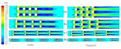
In general, HTRI develops heat transfer and pressure drop correlations useful for heat exchanger design using results from carefully controlled experiments at industrially-relevant scales. Experimental data are always preferable to results from analytical techniques, including CFD. HTRI’s extended surface data cover bundles with common longitudinal-to-transverse pitch ratios up to 2.0. Occasionally, however, our methods are used to design bundles with larger longitudinal-to-transverse pitch ratios—up to 10.0 or higher. To extend our methods in the absence of experimental data, we completed three-dimensional CFD simulations of inline and staggered layouts for an example air cooler at four values of the longitudinal-to-transverse pitch ratio up to 8.4. Velocity contours from the simulations are illustrated below.
Using the trends from the CFD results, we improved the methods in our air cooler and economizer design program Xace for large longitudinal spacing. The effort illustrates that a validated CFD tool allows engineers to understand trends and reduce risk when extrapolating correlations beyond the range of the underlying experimental data.

