Finding a means of limiting NOx from fired heaters, especially under stringent environmental regulations, has become a major concern for the petroleum refining industry. Current regulations from the Texas Commission on Environmental Quality for the Houston/Galveston area have raised the bar: an 80% reduction in NOx levels. A 90% reduction may be in the future. To comply, its essential that every aspect of the burner be optimized to reduce emissions levels. As expected, new projects offer opportunities for process improvements such as reducing maintenance and promoting safety.
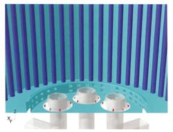
Complying with this new regulation, a refinery upgraded the burners in one of its large cylindrical furnaces. Six ultra-low-NOx round flame burners were retrofitted, each firing 8.44 million BTUs per hour.
Figure 1. Six low NOx burners as modeled for the refinery furnace.
The furnace has process tubes vertically installed along the outside perimeter. The new burners in the vertical-cylindrical furnace have both primary- and secondary-stage fuel injection ports, with the primary stage indicated in yellow and the secondary stage in red in Figures 1, 2 and 3. A draft tube, concentric with the burner block and shown in purple in the center of the closed caption in Figure 1, is used to improve flow uniformity.
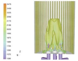
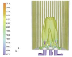
The new burner installation created unexpected and undesirable flame merging. The flame lengths were too long, causing high temperature peaks, which led to excessive NOx emissions. The length of the flame is often a critical burner parameter that plays a role in heat transfer uniformity to the process tubes. Rapid mixing of the fuel and air generates short flames that may lead to unacceptable heat transfer profiles, i.e., high coil temperature. Producing a fat flame may have other consequences: high peak temperatures and high NOx. However, if the flame is too long, it may impinge on the convection section and reduce coil life.
In this furnace, we observed that the flames from the different burners were coalescing into a single flame, producing a large ball of fire with high temperature gradients. The burner interactions significantly increased the length of the flame. This adversely affected NOx. Refinery engineers wanted a uniform temperature profile. They believed that this could be achieved by separating the flame into its individual components.
Figure 2. Burner interactions increased flame length and residence time, and caused spikes in temperature.
Beyond the temperature profile issue there were other concerns that are unique to oil refineries.The majority of NOx formed from the firing of gaseous refinery fuels results from the thermal fixation of atmospheric nitrogen and oxygen. When residual fuel oil is fired, on the other hand, the contribution of fuel bound nitrogen can be significant or even predominant. The primary mechanism for NOx formation in this case is thermal NOx, and the rate of formation primarily depends on the reaction time, local stoichiometry and residence time. Long residence times at high temperatures greatly increase thermal NOx formation.
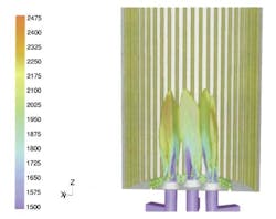
Figure 3. CFD modeling provided the tools for the burner solution.
Art or science?
Until recently, combustion was considered to be more of an art than a science. When NOx levels were too high, the traditional approach was to modify the burners to incorporate well-established emissions reduction techniques, test them and, then, based on the results, fine tune the modifications until desirable results were achieved. The problem with this approach was that the modifications are often expensive and may take a considerable amount of time to implement.
Even more costly, and unacceptable to most operations, is the need to shut down the process at various times during the modification process to install new equipment. Finally, this approach often requires many build-and-test iterations because lack of diagnostics in production furnaces yields limited performance data for analysis. For example, its difficult or impractical to measure gas composition and mixing while simultaneously estimating flow patterns within a production furnace. Knowing both the combustion and flow is critical to understanding flame interaction problems.
Recent improvements in experimental and analytical tools have enhanced the understanding of combustion processes. One of these tools is computational fluid dynamics (CFD).
CFD has been derived from computer assisted drafting (CAD) modeling software. Once a model is created, streamlines of fluid flow can be developed showing the dynamic behavior of these properties. Pressure, flow, temperature and species profiles can be created.
Engineers can use CFD to analyze, in a virtual environment, how design changes affect performance. In combustion, CFD allows the user to see outcomes that would be difficult or impossible to measure in an experimental setting. Flow visualization is a useful tool for identifying potential problems and evaluating multiple solutions expeditiously.
Virtual experimentation
A CFD simulation provides fluid velocity, temperature and chemical concentrations throughout the solution domain for systems with complex geometries. As part of the analysis, a designer may change the geometry of the system or the boundary conditions and view the effect on fluid flow patterns. For these reasons, CFD makes it possible to identify equipment problems far more easily than physical experiments. It also allows the analyst to evaluate the performance of a wide range of different configurations in a shorter amount of time and at a lower cost. Simulation seemed the way to go for our refinery furnace problem.
John Zink selected FLUENT CFD software from Fluent Inc., Lebanon, N.H., because the software has comprehensive combustion modeling tools and has become the analysis standard in the combustion industry. In a wide range of problems, engineers have found the software to be capable of providing predictions that closely match experimental measurements.
John Zink already had some experience with simulation software. Engineers had used GAMBIT, FLUENTs preprocessor, to create a full-scale numerical model of the existing furnace and surrounding ductwork. A key advantage of FLUENT and GAMBIT is the ability to handle unstructured/hybrid meshes. This feature greatly reduces the time needed to create a mesh for the CFD model. The actual fluid physical properties were used in the simulation, and solution-based mesh adaptation tools in the FLUENT solver locally refined the grid in regions where the flow domain required higher resolution. It took about two weeks to completely model the furnace.
The CFD simulation of the original model closely matched the observations of the operating furnace in showing the flames from the individual burners coalescing into a single flame. This gave us confidence in the accuracy of the model. Looking at the flow velocities, pressure distributions and chemical species concentrations predicted by the simulation, we identified an unusually high proportion of unburned fuel within the inner circular area formed by the burners, indicating that there was poor mixing of the fuel and air.
The unmixed fuel didnt burn until it had migrated out toward the end of the flame, creating the flame definition problem. Based on this insight, we reduced the amount of fuel and increased the air to the inner circular area. We hoped that we could achieve a balance. Mechanically, this was accomplished by biasing the primary and secondary fuel injectors.
The first iteration showed a considerable improvement. We viewed the results and noticed that a fair amount of unmixed fuel still remained in the inner circle. Eliminating the fuel was the goal of the second iteration. After about a dozen virtual experiments, we modified the design and optimized fuel/air mixing throughout the furnace. The simulation predicted that the final design would provide excellent flame definition and temperature uniformity. We showed the results to the customer, who was very pleased.
The refiner wasnt looking forward to a long and disruptive experimental process to fix the problem. The customer approved the new design and John Zink produced the modified components. The retrofit was completed on the fly, avoiding furnace shutdown. Our new design worked exactly as predicted, reducing flame length to the desired levels and lowering NOx emissions to acceptable levels. Using CFD visualization required about 12 weeks to identify a solution, without disrupting current operations.
A bright future ahead
Where do we go from here? CFD software will make it possible to avoid customer headaches, to analyze burner changes in advance. These headaches include: shortened coil life from over-temperature excursions, poor material choices, combustion inefficiency, changes in fuel composition, and others. Although the initial cost of this type of study seems daunting for all but critical applications the price can be expected to decrease as those who use it become more familiar with it. Then again, the cost of lost production and the specter of safety and environmental issues resulting from furnace failure may outweigh concerns about the cost of simulation. For more information on CFD and combustion systems visit http://www.fluent.com and www.johnzink.com.
Roberto Ruiz is a vice president of technology and commercial development at John Zink Company in Tulsa, Okla.; e-mail him at [email protected].


