Membrane Boasts Material Benefits
Economical separation of contaminants (e.g., CO2 and H2S) from natural gas is becoming increasingly important as companies look to commercialize lower quality gas fields. CO2 separation can be accomplished using one of several different methods, including cryogenic distillation, recirculating solvent systems or selectively permeable gas-separation membranes. Membranes offer potential advantages over other methods in compactness, simplicity and reduced cost. Recently, membranes based on inorganic or ceramic materials have been developed. These new membrane materials promise to provide better performance and a wider operating-temperature range than available polymer membranes.
At the wellhead, temperatures up to 300°F have been measured, yet conventional polymer membranes can handle a maximum operating temperature of about 150°F. Another issue is that CO2 used for enhanced gas recovery must be re-injected into ground at high pressure, which makes it beneficial to perform the separation at higher pressures than polymer membranes can withstand.
Inorganic membranes have the potential to overcome these problems. Such membranes typically can handle temperatures up to 500°F or 600°F, which is considerably higher than any temperatures reached by producing wells. In addition, they can withstand much higher pressures than polymer membranes so they can be operated at a substantially higher mass flow rate per unit of surface area.
Inorganic membranes are thin films that generally are synthesized on a porous structural support. The membrane and its support structure are mounted in a module that can be easily connected to the feed and outlet streams. In a typical application, the feed stream contains a mixture of gases such as CH4 and CO2. The membrane usually is designed to allow the CO2 to rapidly pass through while effectively blocking the CH4.
Relatively constant flow and chemical species distribution over the full surface area of the membrane is required to obtain high separation performance. Researchers at ExxonMobil have made significant improvements in laboratory-scale inorganic membranes by modeling gas flow across the membrane surface using Computational Fluid Dynamics (CFD). Such simulations have provided insights into improving distribution and effectively using surface area.
Membrane module design challenges
The goal of module design is to fully use all of the available membrane surface area to maximize throughput. There are several design objectives involved in this effort all revolve around the idea of keeping the gases well mixed on the feed side of the membrane.
First, the feed gas flow rates should be evenly distributed across the membrane surface to avoid the formation of dead zones that quickly become depleted of CO2. Within these localized dead zones, the membrane surface becomes inactive because its not replenished with a fresh gas mixture. Second, turbulence is beneficial near the membrane surface because it helps maintain a sufficient concentration of CO2. Third, the so-called stage cut effect, in which the mixed gas feed rate is too low to take advantage of the full surface of the membrane, should be minimized. If, for example, most of the CO2 gas is depleted near the inlet of the module, then the remaining membrane surface effectively becomes inactive. At higher feed-gas flow rates, this effect is reduced.
In the past, designers of membranes used scale models to evaluate the performance of each design. However, there are several problems with this approach. Its time-consuming and expensive to build and test each design being considered. Also, while physical tests generally do a good job of measuring the overall performance of the membrane module, they often cant capture the flow details inside that play such an important role in the modules performance. As a result, engineers often have to guess at the reason behind the performance of a particular design and rely on intuition and experience in an effort to improve it.
In recent years ExxonMobil engineers have been using CFD to improve membrane module design. A CFD simulation provides fluid velocity, pressure, temperature, gas composition and other variables, as appropriate, throughout the solution domain for problems with complex geometries and boundary conditions. As part of the analysis, an engineer may change the geometry of the system or the boundary conditions and then observe the effect of the changes on fluid flow patterns or distributions of other variables such as gas composition. CFD overcomes the traditional difficulties of membrane module design by making it possible to quickly and inexpensively evaluate design alternatives. It also gives a host of diagnostic information.
The performance of several proposed laboratory-scale module designs was evaluated using Fluent CFD software from Ansys, Inc., Canonsburg, Pa.. One of the most challenging parts of the process was modeling the rate at which CO2 molecules pass through the membrane surface. This was accomplished by writing a user-defined function (UDF) that moves CO2 molecules across the membrane based on the pressure and CO2 concentration gradients. The performance of the UDF was validated by simulating the performance of a membrane module that had been built and tested in the laboratory. Predictions from this CFD simulation matched the laboratory test results.
Optimizing the design
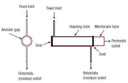
The original module design (Figure 1) consists of a membrane on a hollow tubular support inserted into a cylindrical housing of slightly larger diameter. The feed, a CO2 and CH4 gas mixture, is injected into the annular space between the membrane surface and the module housing through a small tube perpendicular to the modules outer surface. As the feed gas mixture travels along the length of the annulus, the CO2 passes through the membrane into the cylindrical space inside the support. It then exits through a separate permeate outlet at the downstream end. The remaining gas mixture reaches a residue outlet at the downstream end of the annulus, consisting of another small tube attached perpendicular to the modules outer surface.
Figure 1. A single radial inlet leads to flow maldistribution.
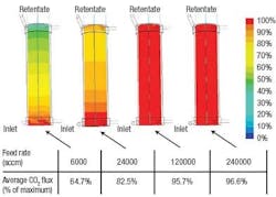
CFD simulations indicated that dead zones with very low surface velocities were occurring in certain sections of the module. Within these dead zones, fresh gas feed isnt brought to the membrane surface quickly enough, so the CO2 flux through the membrane is reduced (Figure 2). Based on these results, it was estimated that the dead zones collectively cut the overall efficiency of the membrane module by approximately 50%. The simulation also showed that the CO2 was essentially depleted from the feed gas well before reaching the outlet end of the module a large portion of the membrane was doing little work.
Figure 2. The normalized CO2 flux of the original module indicates large dead zones at low feed rates.
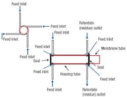
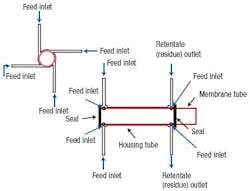
A revised module was designed with four tangential inlets evenly spaced around the circumference of the housing tube to improve the flow distribution around the circumference (Figure 3). A similar change was made at the outlet end of the module.
Figure 3. Changing the inlet and outlet configurations eliminates problems in the original module.
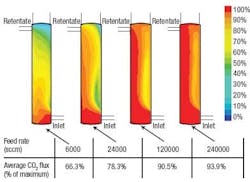
A CFD simulation of the revised design showed improved performance (Figure 4). Compared to the original design, the maximum localized CO2 flux is approximately the same. However, the average flux across the entire membrane surface is approximately 4% to 5% higher at intermediate flow rates. This performance enhancement is attributed to the reduction of dead zones in the revised design. Because of the swirling flow effect created by the tangential inlet/outlet ports more of the membranes surface is engaged in separating CO2.
Figure 4. Even at low feed rates, CO2 is evenly distributed over the media surface in the revised design.
Obviously, operating at high pressure and velocity makes the most of the membrane surface area. Further improvements in membrane module performance could be achieved by increasing internal mixing to reduce the occurrence of dead zones.
Both the original and revised membrane module designs were tested in the laboratory under similar conditions. The relative performance of the two module designs closely matched the trends predicted by the CFD models.
ExxonMobil has used polymeric membranes in production facilities for gas separation but hasnt yet used ceramic-based membranes in such operations. Further research and development work is needed before ceramic membrane materials will become available for commercial-scale gas separation modules.
A potent tool
These results demonstrate that the performance of membranes used for CO2 separation can be substantially enhanced by using CFD to evaluate multiple design alternatives. CFD simulation not only is faster than the alternative of building and testing but offers substantially greater quantities of diagnostic information that can be used to improve the design. As larger and more complex membrane modules are developed for commercialization, CFD is expected to play a key role in their optimization.
Paul J. Rubas is an engineering associate at ExxonMobil in Fairfax, Va., and Kevin Geurts is a senior engineering specialist at ExxonMobil in Houston. E-mail them at [email protected] and [email protected].
