Right Vacuum Control Choice Takes the Pressure Off
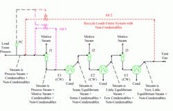
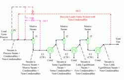
Figure 1. Recycle streams can come from a variety of places including the first-stage discharge and from downstream of the after-condenser.
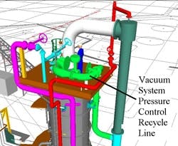
Figure 2. Low-pressure-drop stream requires a large line and control valve.
The most important part of control system design lies in selecting what you’ll manipulate to meet desired objectives. There must be an underlying physical linkage based on process fundamentals between the manipulated part of a system and the control target. The choice affects the effectiveness of control but also can impact process design.
Consider the three-stage steam-jet ejector system shown in Figure 1. The control objective is to run the minimum pressure in an upstream distillation tower but to avoid flooding the tower by dropping the pressure too low. The control scheme relies on regulating the suction pressure to the first-stage ejector.
The fundamental linkage affecting suction pressure is ejector load. Performance curves show variation in suction pressure versus flow rate to the ejector. Standard curves use a basis of either water vapor equivalent rate (recent units) or dry air equivalent load (older units). The equivalent load is determined by applying entrainment ratios to correct for suction temperature and suction molecular weight.
Three factors alter the equivalent load: suction temperature, suction molecular weight and suction mass rate. For the common situation in which the process load delivered to the ejector isn’t a variable, we must use a stream within the ejector system to change the equivalent load.
Don’t alter the motive steam delivery pressure unless you’ve absolutely no other choice. For a new system, always use internal recycle within the unit or deliberately add load (steam injection into the process suction).
Figure 1 shows two extreme options for suction pressure control using internal recycle. Alternative 1 recycles discharge from the first stage. Alternative 2 recycles load from downstream of the after-condenser. However, recycle may come from any vapor stream downstream of the first ejector discharge.
In general, it’s best to recycle the discharge of the first ejector because that stream affects only the first stage. You then can control ejector system pressure without altering net flow to the first inter-condenser (E1). No changes in downstream ejectors (J2 and J3) are required. You can set the entire system for minimum size, capital and operating cost by moving only the net load in downstream ejectors.
On the downside, that stream only has a low pressure drop to recycle from the ejector discharge to the ejector suction — making both the line and the butterfly control valve large, as shown in a computer generated view that also includes a person for scale (Figure 2).
So, using the discharge of the entire vacuum system (Alternative 2) tempts many engineers. The recycle line and control valve are much smaller and cheaper. However, resist the temptation. Using either the after-condenser vapor or the discharge from the third-stage ejector leads to dramatically higher loads on the second- and third-stage ejectors.
As the pressure increases in the stages of the vacuum system, the fraction of the flow made up of non-condensable material rises. Non-condensable load is a small portion of the J1 discharge but, by the time we reach the after-condenser (E3) vent gas, non-condensables comprise nearly the entire stream.
To recycle enough material to allow for control of the first-stage suction pressure, the rate of non-condensable load in the second and third stages will dramatically increase. For this system, the non-condensable load would more than double.
For a new system, the extra non-condensable load makes the second-stage and third-stage ejectors (J2 and J3) and condensers (E2 and E3) dramatically larger. For an existing system, the non-condensable load increase would overwhelm the system’s capability.


