Stripper Bares All
At first, the job seemed simple enough: a quick review of a water stripper to verify size and tray efficiency to make sure the unit would work. In the end, the review wasn’t so simple. We’ll concentrate on two lessons that came out of it.
A tough set of environmental specifications called for less than one weight ppm (wppm) hydrogen sulfide and less than 10 wppm ammonia in the bottoms from the stripper. The objective was to allow sending the stripped water to wastewater treatment or reusing it as process water.
Typical performance specifications for many steam strippers removing ammonia target “guaranteed” performance levels of 100 wppm ammonia, with expected operation varying between 50 wppm and 100 wppm. Consistently achieving ammonia levels of 10 wppm or less is very tough. The equilibrium concentration of ammonia at low solubility levels in water strongly depends upon the water pH.
Designing and operating a unit for such tight specifications presents challenges. The first is what tray efficiency to use — much of the available data are for relatively high ammonia concentrations. Second, little of the reported data come with information on the water pH — this leads to a wide range of tray efficiency results. The plant was prepared to accept using a low tray efficiency and paying for the tall tower required. However, it hadn’t made provision for pH control instrumentation or facilities.
It turned out that the process simulator originally used to set the heat and material balance relied on a Henry’s Law solubility approach with no allowance for pH levels. This may work to predict process requirements for 100 wppm ammonia in water but not for 10 wppm or less ammonia.
Accurate equilibrium calculations of low levels of contaminants in water require accounting for ionic interactions. You can do this either via data developed from the conditions you will have or, at a minimum, calculations using electrolyte thermodynamics to reflect interactions between ion species and system pH.
Further discussion revealed additional important background information. Part of the reason for a new water stripper was that the existing one couldn’t achieve expected capacity. Intermittent tower flooding forced the plant to run at reduced water-treating rates. This is a major danger signal. For most conventional processes, the chemical engineering community has a very good grasp of the fundamentals of the hydraulics of water flow in nearly every type of equipment. Lots of data are available on water (and steam) flow. So, equipment that can’t handle the expected hydraulic rates definitely demands serious investigation.
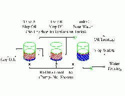
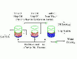
Figure 1 -- Tank Farm: Poor design and practices
fostered pumping of liquid to the wrong tank.
(Click on image for a larger PDF.)
This investigation finally led to the tank farm feeding the water stripper and slop reprocessing (Figure 1). Three gravity-settling tanks handled slop oil and wastewater. At different times, multiple sources from nine separate units could feed the tanks. Inevitably, all three tanks would end up with mixtures of oil and water in them. Two tanks mainly separated trace amounts of water from oil, while the third dealt with small amounts of oil in water.
Interconnecting piping was available to move the water heels from the two oil tanks to the water tank. The same piping moved the oil layer from the water tank to the oil tanks. None of the tanks had instrumentation or connections for interface measurement.
Operators would go into the tank farm and manually start up the transfer pumps when either the wastewater plant or the slop-oil plant got the wrong feed. By that time, it was too late — the water stripper already was flooding from foaming induced by oil in the feed water. At other times as a preventive measure the operators would start up and run the pumps for arbitrary lengths of time. However, they never knew when they might be pumping the wrong liquid into the wrong tank.
Additionally, the common transfer line had a relatively large volume compared to the tanks’ size. Changing the service between oil movement and water movement inevitably put large volumes of the wrong liquid in the wrong tank.
In this case, the source of many of the water-treating problems was the tank farm. Addressing the problems requires interface measurement and correct transfer piping.
The project, as originally conceived, suffered from two major flaws. The first was insufficient understanding of the system chemistry and the limitations of the design tools used. The second was failure to find the root cause of major operating problems. Successful projects require both fundamental knowledge of the process and practical understanding of how installed equipment actually works in the field. Best performance plants fix problems at their source.
Andrew Sloley is a contributing editor for Chemical Processing. You can e-mail him at [email protected].

