Check What You're Ordering
Tray hydraulics is very complicated and involves balancing many competing factors that affect both capacity and flexibility. However, plants often can gain more column capacity by lengthening tray spacing or sloping tray downcomers.
Greater tray spacing increases the distance (and time) available for liquid droplets to fall out of the vapor back into the liquid on the tray. This often suits trays operating in the spray regime, which implies normal-to-low liquid loads, low vapor density and high liquid density.
Sloping the tray downcomers opens up bubbling area on the tray deck. The extra area allows for more valves or holes, decreasing vapor velocity through the tray. Lower vapor velocities reduce tray pressure drop and spray formation if trays are operating in the spray regime.
One plant decided to increase the capacity of its decade-old main fractionator. The column ran at just above atmospheric pressure; vapor densities were low and liquid densities were high. Operation was in the spray regime even though liquid rates were extremely high.
[pullquote]The tower's bottom section was 363.5 in. in diameter in heat transfer service. Liquid was drawn from the tower bottom, cooled and then returned eight trays up as a pump-around heat-removal stream. The cold liquid condensed heavy ends from the feed vapor that entered under tray one. Extremely high liquid rates were required to get sufficient heat removal against medium pressure steam generation used as the pumparound cooling heat sink.
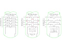
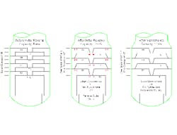
The plant made a series of modifications (Figure 1 shows the major ones) to raise capacity of the fractionator's bottom section. These included:
1. Replacing the original eight trays on 36-in. spacing with six trays — with 60-in. spacing between tray one and tray two and 48-in. spacing between the other trays — while retaining the existing 36-in. spacing to the tray in the next section up;
2. Sloping the downcomers to increase the area available for active panels on the trays below;
3. Using new active panels to take advantage of the downcomer sloping;
4. Cutting off tray outlet weirs; and
5. Installing shaped downcomer lips (not shown) to decrease tray pressure drop.
The changes raised tower capacity by 40%. Plant performance tests confirmed the increase.
In the 16 years since making those modifications, many feed and product quality changes had occurred, creating new bottlenecks. So, the plant launched a second revamp project.
The first step was to re-run tests on major plant constraints. To everyone's surprise, the test of fractionator indicated it was running at only 110% of original design capacity rather than the previously demonstrated 140%. Engineers reviewed plant information in detail but couldn't find any reasons for the reduced capacity.
A scan of the column didn't provide any insights. In fact, the scan results were so contradictory they were useless. (Further investigation showed the execution of the scan was badly botched.)
The only benefit from the scan was that it forced plant personnel to re-check every detail yet again. This led to a significant discovery. A purchase order for replacement tray panels, which had been placed after the first revamp, specified that panels conform to the original drawings for the tower internals. The bubble area added in the revamp had been replaced by solid tray panels.
The return to the original tray panels had undone most of the capacity increase. Feed composition changes had hidden the effect and an extended period of soft market demand had eliminated any immediate need for the lost capacity. When the market rebounded, enough time had elapsed that the capacity drop went unnoticed.
Putting back correct tray panels markedly improved operation.
Accurate equipment records can provide major help in identifying many plant problems. It's our job both to create good records and to look at them in detail as needed.
Andrew Sloley is a Chemical Processing Contributing Editor. You can e-mail him at [email protected].

