Improve Your Refrigeration System
Many people regard carbon dioxide as the most promising refrigerant for several application areas. It's a natural substance with excellent heat transfer properties and when used a refrigerant generally provides opportunities to enhance system energy efficiency and considerably lower overall environmental impact.
However, using CO2 as a refrigerant brings some new technical challenges because both its critical point and triple point fall within the envelope of practical use. In addition, some thermodynamic and transport properties (e.g., saturation pressure level and liquid viscosity) are extreme compared to traditionally used refrigerants (NH3, HCFCs and HFCs). Table 1 compares some properties of select refrigerants relevant to process plants and refrigerant pumps. The most significant differences between CO2 (R744) and the other refrigerants are its low critical temperature, high saturation pressure, very low kinematic viscosity and low surface tension.
In the last 10 years, many technical challenges related to CO2 have been successfully overcome for components such as compressors, valves and heat exchangers. Now, commercially competitive versions of these components designed and optimized for CO2 are available on the market.
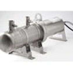
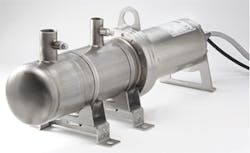
Refrigerant pumps have been offered for 60+ years. Most were typically designed for general chemical industry service and then modified to operate with the substances used as refrigerants (e.g., NH3 and R22). Due to increasing demands for low leakage levels, most refrigerant pumps today rely on canned motors or magnetic couplings. Commercially competitive refrigerant pumps designed and optimized for CO2 have been on the market for less than one year (Figure 1).
PUMP ISSUES
The specific challenges for refrigerant pumps operating with CO2 are:
High system pressure. The saturation pressure of CO2 is much higher than that of the traditionally used refrigerants. At 40°F (4°C) the saturation pressure is 550 psig (38 bar g). Today 750 psig (52 bar g) seems to satisfy most demands -- but in the near future some types of systems will need a maximum system pressure of 950 psig (65 bar g). In addition, standstill requirements for many systems demand a maximum system pressure up to 1,750 psig (120 bar g).
Subcooling from liquid column. A column above the pump inlet changes the liquid refrigerant condition from saturated to subcooled. This ensures that internal losses in the pump's inlet section don't generate vapor that can reduce pump performance. For most traditional refrigerants each foot of liquid column provides considerable subcooling; at nominal operating conditions the net positive suction head required (NPSHR) typically is limited to 3–5 ft (1–1.6 m). For CO2, a 3–5-ft liquid column produces practically no subcooling due to the different relation between saturation pressure and temperature. Therefore, reducing inlet losses and establishing a high degree of hydraulic robustness to vapor bubbles become very important design elements for a CO2 pump.
Low liquid viscosity. CO2's liquid viscosity is lower than that of NH3, HCFC and HFC. For media-lubricated bearings, viscosity is a very important parameter for bearing lifetime.
Low surface tension. CO2's surface tension also is lower than that of NH3, HCFC and HFC. Vapor generated will appear as numerous very small bubbles -- typically creating a foamy mixture instead of a separated liquid and vapor flow.
Low refrigerant temperature. During evacuation, service and charging processes low temperatures occur -- the pressure can drop below the triple point pressure of 75.4 psia (5.2 bar), leading to formation of dry ice. At atmospheric pressure, dry ice sublimates at a temperature of -108°F (-78°C) or below. Temperatures in refrigerant pump environments can reach -150°F (-100°C).
Operation "close" to critical point or triple point. The difference between liquid and vapor density generally is lower for CO2 than for all other refrigerants. As the critical point is approached, the density difference goes toward zero. Therefore, density-difference-driven liquid/vapor separation isn't as effective for CO2 as for other refrigerants. As the condition comes closer to the triple point, dry ice may form inside the pump, potentially damaging canned-motor centrifugal pumps.
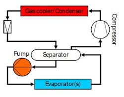
Figure 4. Carbon dioxide serves as the only refrigerant in
such designs.
These challenges call for a pump design with few seals and small dimensions. Hydraulic robustness to vapor in the inlet must be high. Vapor bubbles will form there frequently because liquid subcooling will be practically zero and the vapor and liquid don't separate well. Therefore, cavitation likely will occur often -- but because CO2's surface tension and latent heat of vaporization both are low, it shouldn't have nearly the same damaging effect as it does in water and NH3. The pump should feature materials with cavitation-resistant properties and surfaces, and should handle temperatures down to -150°F (-100°C).
In addition, the pump should satisfy general design requirements such as compactness, light weight, high energy efficiency, variable speed capacity control, easy integration, minimal maintenance needs and easy servicing.
SYSTEM DESIGNS
CO2 can be used as a refrigerant in three fundamental ways:
1. Indirect system. CO2 serves as a secondary volatile refrigerant with circulation established by a mechanical pump. The main drivers for this option are to considerably reduce system energy consumption, significantly decrease primary refrigerant charge when that refrigerant has a high global warming potential (GWP) or is flammable or toxic, and increase system energy efficiency. Studies show that indirect systems with CO2 have the same first cost as traditional systems.
Figure 5. Pump circulates refrigerant throughout pipe network
with evaporators.
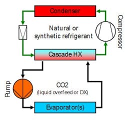
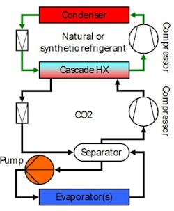
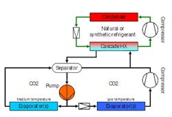
2. Cascade system. CO2 is the refrigerant in the lower-stage part of a two-stage system. This type of system typically appeals where there's a demand for refrigeration at a low temperature level (e.g., in process plants) or at two temperature levels (e.g., in supermarkets). Such a system can also reduce the charge of the primary (upper-stage) refrigerant considerably.
3. Transcritical system. CO2 is the only refrigerant used. Due to CO2's low critical temperature these systems must be designed for a cyclic process in which heat rejection can take place above the critical temperature. As a cyclic refrigeration process, the transcritical system is less energy efficient than the subcritical process and typically also requires higher compressor capacity. Therefore, if high ambient temperatures occur for long periods during the summer the transcritical cycle becomes less attractive.
Figures 2 to 4 show examples of design principles for these types of systems. The indirect system requires refrigerant pumps for circulation of the liquid CO2 to all the evaporators in the pipe network. In both the cascade and transcritical systems, refrigerant pumps can establish refrigerant circulation to all the evaporators in the pipe network but aren't absolutely necessary -- in some system designs internal pressure differences can also be used to circulate the refrigerant. However, pumps often are preferred because they allow liquid overfeed operation of the evaporators.
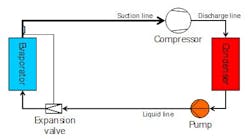
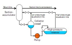
Most refrigerant pumps are used to establish liquid distribution of the refrigerant in the evaporators' pipe network (Figure 5). Such pumps also serve for liquid pressure boosting -- to provide extra pressure differential for expansion valves and to enable energy efficient system operation with low condensing temperatures during cold ambient conditions in winter (Figure 6). In larger industrial refrigeration systems, the pumps also handle general liquid transport between components like receivers and separators at different temperature levels (Figure 7).
OPTIMIZATION OPPORTUNITIES
Pumps designed and optimized for CO2 can offer a number of benefits for refrigeration systems:
Figure 6. Pump provides extra pressure differential for expansion valves.
Reducing direct environmental impact. Using CO2 and refrigerant pumps can decrease the charge of refrigerants negatively affecting the environment. A large part of the environmental impact of industrial refrigeration systems comes from permanent leaks and accidental release of refrigerants. Annual leak rates can reach 30% of the system charge, causing considerable direct impact. CO2 has a GWP of only 1 while many HFCs have GWPs up to several thousands (e.g., GWP for R134a is 1,300).
Decreasing energy consumption by improving operating conditions. Using refrigerant pumps to establish forced circulation and liquid overfeed operation of evaporators can increase evaporator energy efficiency. This allows a rise in evaporation temperature, which is one of the most important parameters for boosting overall energy efficiency of the refrigeration system. Depending on evaporator type, the refrigerant and the operating conditions, an increase of 4–8°F (-15– -13°C) is possible. As a rule of thumb, a refrigeration system's energy consumption goes down by approximately 2% for each °F the evaporating temperature goes up.
Figure 7. Pump can also handle more general duties in larger systems.
Cutting refrigerant-pump energy consumption by better capacity control. Only a few systems operate with a constant refrigeration load -- therefore, effective capacity control of the refrigerant pump is important for performance and energy optimization. Not all capacity-control options decrease pump energy consumption. The use of a frequency converter and closed loop control of the pressure difference generated by the pump is one of the most attractive methods because it significantly reduces the pump's energy consumption.
Lessening refrigerant-pump energy consumption by better pump protection. The design of refrigerant pumps and the risk of vapor entering or forming inside the pump usually restrict the accepted operating envelope. By tradition, loss-generating protective devices such as permanent bypasses or Qmax orifices (to prevent too-high flows that could cause cavitation) have protected refrigerant pumps from operation outside the accepted envelope -- but at the cost of significant energy losses. A pump designed for CO2 coupled with intelligent electronic controls can obviate these protective devices and the losses they incur. Such electronic controls also enable improved monitoring of operations and regulating pump capacity and bypass in an intelligent way.
Field trials that employed all these measures achieved cuts in pump energy use on the order of 60–70%. Pump energy demand fell from a level of 6–7% of system energy consumption to just 2–3% [2].
BJARNE DINDLER RASMUSSEN is global product manager – refrigerant pumps for Grundfos Pumps, Olathe, Kan. Email him at [email protected].
References
1. "Engineering Equation Solver," version 8.684, F-Chart Software, Madison, Wisc. (Oct. 2010).
2. Rasmussen, B. D. and Pachai, A. C., "Energy Saving Potential of Controlled Refrigerant Pumps in CO2/R404A-cascade systems," p. 987, Proceedings, 8th IIR Gustav Lorentzen Conf. on Natural Working Fluids, Copenhagen, Denmark (2008).
