Get Full Value from Partial Condensers
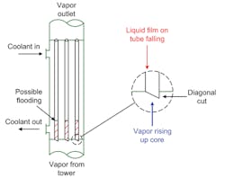
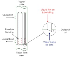
Partial condensers must handle two product streams — vapor and liquid. One variant (Figure 1) sometimes is installed at the top of a distillation tower. In this vertical updraft design, vapor enters the condenser tubes at the bottom and flows toward the top. The condensed liquid flows down the condenser tubes and drops back down to the tower below. This counterflow can enable extra refluxing and mass transfer.
[pullquote]
A vertical updraft exchanger can eliminate piping, pumps and drums. It particularly suits towers with a partial condenser and a vapor product overhead. Design and operation of the unit, which sometimes is called a “dephlegmator,” must account for both heat transfer and mass transfer.
One limiting factor with these exchangers is potential flooding at the vapor inlet to the tube. The gas entering the exchanger tube imposes a drag force on the liquid flowing down. Sufficient drag force can cause a liquid layer to build up. When the liquid layer becomes too large, the tubes flood. (You can confirm flooding by measuring exchanger pressure drop while reducing unit capacity. When flooding stops, pressure drop suddenly decreases.)
Figure 1. In effect a refluxed heat exchanger, this unit can provide extra mass transfer.
Flooded tubes can create many problems, including high pressure drop in the tubes, entrainment of liquid in the vapor outlet, and vibration or other issues from cyclic filling and dumping of liquid from the tubes.
Allowing the tubes to extend slightly from the tubesheet and cutting their ends at an angle helps liquid drain from the tubes. The tube extension increases vapor pressure drop entering the tube — but this rarely is significant.
Even with angle-cut tubes, there is a prudent limit to upper vapor velocity entering the tube. So, you should check the actual velocity, Vactual, against flooding velocity, Vflood, particularly when problems arise.
[callToAction ]
First, determine the critical ratio, Rc,
Rc = dc/di
where diis the tube inner diameter in inches, and dc is the critical diameter, which is a measure of the liquid’s ability to bridge the tube due to surface tension, in inches.
dc = σ/80
where σ is surface tension in dynes/cm.
Then, determine a correlating factor, F1:
F1 = 1.0 for Rc ≥1.0
F1 = (di/dc)0.4 for Rc <1.0
You also need a second correlating factor, F2, which is based on the mass flow rates of vapor, G, and liquid, L, in consistent units:
F2 = (L/G)-0.25
Then, you can calculate a flooding factor, P, to account for the drag force of the gas based on its density and the tendency of surface tension to bridge the tube:
P = F1F2(σ/ρg)0.5
where ρg is the density of the gas entering the tube in lb/ft3.
This allows calculating the flooding velocity, Vflood, which is based on a mixed phase mass density at the bottom of the tube:
Vflood = P for P≥10
Vflood = 0.71P1.15 for P<10
(J. E. Diehl and C. R. Koppany, Chemical Engineering Progress Symposium Series, Vol. 65, No. 92 (1969))
Compare this to Vactual:
Vactual = Gm/ρaverage
where Gm is the vapor mass flux in lb/ft2-sec based on tube inside cross-section and ρaverage is the average density based on the combined flow of vapor entering the tube and liquid leaving the tube.
As a general rule, if Vactual ≤ 0.83 Vfloodthe exchanger is unlikely to have flooded tubes where the gas enters.


