Free Up More Tubular Exchanger Area
[pullquote]Design margins incorporated in most plants and equipment often offer a cost-effective way to increase asset utilization. Over time, a site can use design margins to raise plant capacity or improve product quality. However, constraints posed by just one or two items frequently hinder overall improvements — and make debottlenecking that equipment important.
One recent example was a plant that wanted to raise product yields at its current capacity. Key to that was heating the feed to a higher temperature. The feed was heated by a combination of heat integration followed by a fired heater. The plant already was using all the spare duty capacity of the fired heater. So, the most straightforward approach to get the additional duty required was to modify the heat integration system.
The heat integration exchangers were installed in a multi-level structure. Code limitations precluded adding significant weight to that structure. In addition, the site only had limited open area suitable for new equipment.
Modifications targeted two elements. First, pinch analysis showed that one exchanger in the existing heat integration was nearly completely ineffective. Removing that exchanger would open up both space and weight capability for installing a much-more-effective heat integration unit. Second, minor changes — even as little as 5–6% more duty in specific services — would provide significant benefits. So, here, we’ll look at how the plant got this extra duty from a heat exchanger.
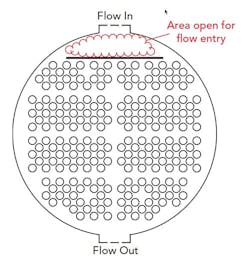
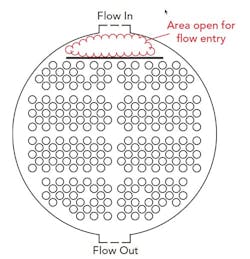
Figure 1. Open area under the inlet nozzle for velocity reduction robs area available for the exchanger bundle.
Figure 1 illustrates the tube-sheet layout of one exchanger in the plant. It is a partial-condensing exchanger with hot fluid (vapor) on the shell side and cold fluid (liquid) on the tube side. The exchanger is a TEMA E-type shell with eight passes on the tube-side, and downward shell-side condensing flow. The pinch analysis showed that nearly all exchangers in the plant, including this one, were surface area limited. Adding surface area would increase exchanger duty most effectively.
Perhaps the most obvious change would have been to switch the bundle pitch from rotated square to triangular. This would have allowed more tubes, increasing surface area. However, because the exchanger was in a fouling service, the benefits of easier cleaning of the rotated-square pitch outweighed the additional surface area possible with a triangular pitch.
Immediately downstream of the exchanger’s inlet nozzle is an open area with no tubes and an impingement plate. If tubes are too close to the inlet nozzle, they block a large fraction of the flow area, creating pressure drop and high inlet velocities. The open area between the inlet nozzle and tube bundle allows the vapor to flow along part of the shell length before entering the tubes. Effectively, this increases the inlet area for vapor flow into the bundle.
The impingement plate prevents high velocity vapor from jet-impinging onto the tubes. The vapor contains some liquid droplets, so high velocity impingement could cause erosion or other mechanical damage.
Providing open area under the inlet nozzle is a conventional approach in exchanger design. Open area also is used next to the outlet nozzle if high velocities are expected there as well. In this case, the tube removal reduces the area possible in that shell diameter by approximately 6%. So, decreasing the inlet velocity another way would allow replacing the exchanger bundle with one having 6% more area.
Two other methods of inlet velocity reduction are possible: a dome at the inlet; or a vapor belt that circles, or partially circles, the shell to allow vapor into the bundle at multiple locations. Both increase the inlet area open for flow and decrease inlet velocity.
Here, the plant opted for a vapor belt because it required fewer external piping modifications. Both the vapor belt and the extra tubes added weight to the exchanger. Keeping the weight within the allowable limit required making the tubes and tube sheet of thinner material.
While the modifications may seem extreme for just 6% more duty, the extra feed heat was critical and allowed for more product recovery.


