1211-insites-ts

Backflush Away Fouling

Nov. 6, 2012
Flow reversal can remove fiber buildup in heat exchangers.

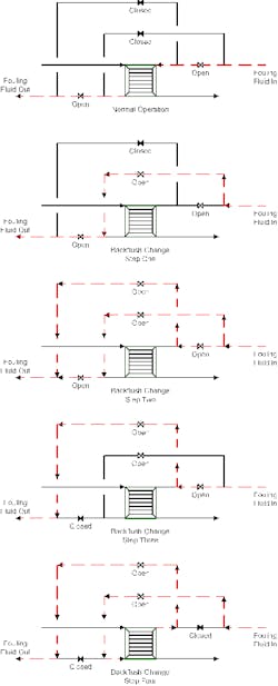
Fouling services present difficult challenges for heat exchangers. Fouling can result from reactions, sticky materials, solidification and many other causes. In biofuels plants, fibers often lead to fouling problems. Backflush operation can reduce the effect of fouling in these plants.

There are two approaches to backflush. In a short-period backflush, which can last from a few minutes to a few hours, flow direction is reversed to dislodge fibers; then, the regular flow pattern is re-established. In a long-period backflush, which can extend for days to months, the exchanger is operated with flow in the reverse direction until it fouls again; then, flow is switched back to the normal direction to dislodge the second round of fiber fouling.

BACKFLOW ARRANGEMENT
Figure 1.Four-step procedure and design details ensure a safe and effective backflush.A plate-and-frame exchanger in a new biofuels plant required a short-period backflush to reduce the maintenance load in cleaning the plates. Figure 1 shows the backflush configuration on one side of the unit; the other side has a comparable setup.The backflush procedure consists of four steps:1. Open the supply bypass around the exchanger. At this point, the fouling fluid completely bypasses the exchanger.2. Open the exit bypass around the exchanger. Now the fouling fluid goes through both bypasses.3. Close the normal flow line exit side valve. The fouling fluid still bypasses the exchanger.4. Close the normal flow line supply-side valve. Now the flow is reversed and backflush begins.At no time is the exchanger blocked in. This is important. A blocked-in side might fail from thermal expansion or vaporization (depending upon temperature profiles). Never allowing a side to be blocked in prevents many problems.A successful bypass here also requires attention to other details.Because the bypass lines may lack flow for extended periods, valves are located at high points to help reduce the possibility of solids' accumulation. Additional modifications to handle the solids include installing full-bore flush valves as close as possible upstream and downstream to all block valves. The flush valves are mounted on the top of the lines to prevent solids' accumulation. (Water can flush any plugs out of the lines.)Thermal relief valves also are necessary to prevent exchanger rupture due to accidental closing of isolation valves and fire exposure contingency.Under some conditions, fouling may be so severe that the backflush doesn't work effectively. So, the layout must allow for quick swapping out of an exchanger. The bypass lines enable either running without an exchanger installed for a short period or a quick switch to a spare unit.One initial concern was unit control stability when removing the exchanger from service. The process requires operation at a specific temperature. The heat-integration system can handle one out-of-service exchanger at a steady-state condition. However, dynamic response when removing the exchanger is a different matter. Some questions arose about how stable the entire system would be under the backflush conditions.In this case, backflush only occurs when heat transfer is so low that removing the exchanger incurs negligible loss of duty. A more serious concern is process response once the exchanger is suddenly much cleaner — but experience in this system shows no problems.The backflush installation works well for this service. Economics were reasonable despite the number of valves and the amount of piping involved. The backflush keeps the exchangers cleaner at relatively little maintenance cost. Taking the exchanger apart for mechanical cleaning would be much more expensive.Consider backflush particularly for removal of fibrous or easily dislodged material. It provides little benefit for sticky fouling or polymer deposits.

ANDREW SLOLEY is a Chemical Processing Contributing Editor. You can e-mail him at [email protected]

Sponsored Recommendations

Heat Recovery: Turning Air Compressors into an Energy Source

More than just providing plant air, they're also a useful source of heat, energy savings, and sustainable operations.

Controls for Industrial Compressed Air Systems

Master controllers leverage the advantages of each type of compressor control and take air system operations and efficiency to new heights.

Discover Your Savings Potential with the Kaeser Toolbox

Discover your compressed air station savings potential today with our toolbox full of calculators that will help you determine how you can optimize your system!

The Art of Dryer Sizing

Read how to size compressed air dryers with these tips and simple calculations and correction factors from air system specialists.